ros2_control — Bridge Between ROS 2 and Real Hardware
After building a URDF and TF2 in Part 4, the next question is always: how do I control real motors? This is where ros2_control shines. This framework provides a standardized abstraction layer between controllers (control algorithms) and hardware interfaces (hardware communication), allowing you to decouple control logic from specific drivers — write it once, use any standard controller.
This article continues the ROS 2 series — if you haven't read them, start with Part 1: Setup and First Node, Part 2: Topics, Services and Actions, Part 3: Parameters, Launch and Lifecycle, and Part 4: TF2, URDF and RViz2.
Version (June 2026): This article uses ROS 2 Jazzy Jalisco (LTS, Ubuntu 24.04) — the most stable choice for beginners. The commands work the same on Kilted Kaiju and the newest LTS Lyrical Luth (May 2026). If you're still on Humble (Ubuntu 22.04), just swap
jazzy→humblein package names.
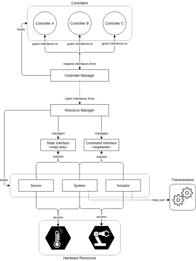
ros2_control Architecture
ros2_control has 3 main components working together:
┌─────────────────────────────────────────────────┐
│                Controller Manager                │
│  (Load, configure, activate controllers)         │
├──────────────┬──────────────┬───────────────────┤
│ joint_state  │ forward_cmd  │ diff_drive        │
│ _broadcaster │ _controller  │ _controller       │
│              │              │                   │
│ (read state) │ (send command)│ (diff drive)     │
└──────┬───────┴──────┬───────┴──────┬────────────┘
       │              │              │
       │    Command & State interfaces
       │              │              │
┌──────▼──────────────▼──────────────▼────────────┐
│              Hardware Interface                   │
│  (SystemInterface / ActuatorInterface /           │
│   SensorInterface)                               │
├─────────────────────────────────────────────────┤
│  read() → read encoders, IMU                     │
│  write() → send PWM, velocity command            │
└──────────────────┬──────────────────────────────┘
                   │
          ┌────────▼────────┐
          │   Hardware      │
          │  (Motor, Encoder│
          │   IMU, Gripper) │
          └─────────────────┘
Core Concepts:
| Concept | Role |
|---|---|
| Controller Manager | Central node, manages lifecycle of all controllers |
| Hardware Interface | Plugin communicates directly with hardware via serial/CAN/SPI |
| State Interface | Read state (position, velocity, effort) from encoders/sensors |
| Command Interface | Send commands (position, velocity, effort) to motor drivers |
| Controller | Control algorithm — reads state, calculates, sends command |
Install ros2_control
# Install ros2_control packages
sudo apt install -y \
  ros-jazzy-ros2-control \
  ros-jazzy-ros2-controllers \
  ros-jazzy-controller-manager \
  ros-jazzy-joint-state-broadcaster \
  ros-jazzy-forward-command-controller \
  ros-jazzy-diff-drive-controller

# For mock hardware testing
sudo apt install -y ros-jazzy-ros2-control-test-assets
New in ros2_control (Jazzy → Lyrical Luth, as of June 2026):
- Controller chaining — chain multiple controllers (e.g. admittance → trajectory → forward) for easier modular reuse.
- Wildcard entries in controller config files — compact declarations for many controllers of the same type.
--controller-ros-argsfor thespawner— remap the controller node's topics/services at spawn time.- Multiple
-p/--param-fileper spawner — load several param files for one or many controllers. - Introspection via the
REGISTER_ROS2_CONTROL_INTROSPECTIONmacro — inspect a controller's internal variables while debugging.
Official docs: control.ros.org.
Step 1: Describe Hardware in URDF
ros2_control uses <ros2_control> tags in URDF to declare hardware interfaces. Here's an example for a 2-wheel differential drive robot with DC motors and encoders:
<!-- ~/ros2_ws/src/my_robot_hardware/urdf/robot.urdf.xacro -->
<?xml version="1.0"?>
<robot xmlns:xacro="http://www.ros.org/wiki/xacro" name="my_diff_robot">

  <!-- Base link -->
  <link name="base_link">
    <visual>
      <geometry><box size="0.3 0.2 0.1"/></geometry>
    </visual>
  </link>

  <!-- Left wheel -->
  <link name="left_wheel">
    <visual>
      <geometry><cylinder radius="0.05" length="0.04"/></geometry>
    </visual>
  </link>
  <joint name="left_wheel_joint" type="continuous">
    <parent link="base_link"/>
    <child link="left_wheel"/>
    <origin xyz="0.0 0.12 0.0" rpy="${-pi/2} 0 0"/>
    <axis xyz="0 0 1"/>
  </joint>

  <!-- Right wheel (similar) -->
  <link name="right_wheel">
    <visual>
      <geometry><cylinder radius="0.05" length="0.04"/></geometry>
    </visual>
  </link>
  <joint name="right_wheel_joint" type="continuous">
    <parent link="base_link"/>
    <child link="right_wheel"/>
    <origin xyz="0.0 -0.12 0.0" rpy="${-pi/2} 0 0"/>
    <axis xyz="0 0 1"/>
  </joint>

  <!-- ros2_control hardware interface -->
  <ros2_control name="DiffDriveSystem" type="system">

    <!-- Plugin: use custom or mock -->
    <hardware>
      <plugin>my_robot_hardware/DiffDriveHardware</plugin>
      <param name="serial_port">/dev/ttyUSB0</param>
      <param name="baud_rate">115200</param>
      <param name="encoder_ticks_per_rev">1440</param>
      <param name="wheel_radius">0.05</param>
    </hardware>

    <!-- Left wheel joint -->
    <joint name="left_wheel_joint">
      <command_interface name="velocity">
        <param name="min">-10.0</param>
        <param name="max">10.0</param>
      </command_interface>
      <state_interface name="position"/>
      <state_interface name="velocity"/>
    </joint>

    <!-- Right wheel joint -->
    <joint name="right_wheel_joint">
      <command_interface name="velocity">
        <param name="min">-10.0</param>
        <param name="max">10.0</param>
      </command_interface>
      <state_interface name="position"/>
      <state_interface name="velocity"/>
    </joint>

  </ros2_control>

</robot>
Explanation:
type="system"— SystemInterface manages multiple joints simultaneously (good for diff drive, robot arms)command_interface name="velocity"— controller sends velocity commandstate_interface name="position"and"velocity"— hardware returns position and velocity from encoder<param>elements inside<hardware>are read in C++ plugin code
Step 2: Write Custom Hardware Interface (C++)
This is the most critical part — write a plugin to communicate with real hardware via serial:
// ~/ros2_ws/src/my_robot_hardware/src/diff_drive_hardware.cpp
#include "hardware_interface/system_interface.hpp"
#include "hardware_interface/handle.hpp"
#include "hardware_interface/hardware_info.hpp"
#include "hardware_interface/types/hardware_interface_return_values.hpp"
#include "rclcpp/rclcpp.hpp"
#include <serial/serial.h>  // libserial

namespace my_robot_hardware
{

class DiffDriveHardware : public hardware_interface::SystemInterface
{
public:
  // Initialization — read params from URDF
  hardware_interface::CallbackReturn on_init(
    const hardware_interface::HardwareInfo & info) override
  {
    if (SystemInterface::on_init(info) != CallbackReturn::SUCCESS) {
      return CallbackReturn::ERROR;
    }

    // Read params
    serial_port_ = info_.hardware_parameters["serial_port"];
    baud_rate_ = std::stoi(info_.hardware_parameters["baud_rate"]);
    ticks_per_rev_ = std::stoi(info_.hardware_parameters["encoder_ticks_per_rev"]);
    wheel_radius_ = std::stod(info_.hardware_parameters["wheel_radius"]);

    // Initialize variables
    hw_positions_.resize(2, 0.0);
    hw_velocities_.resize(2, 0.0);
    hw_commands_.resize(2, 0.0);

    return CallbackReturn::SUCCESS;
  }

  // Open serial connection when activated
  hardware_interface::CallbackReturn on_activate(
    const rclcpp_lifecycle::State &) override
  {
    try {
      serial_.setPort(serial_port_);
      serial_.setBaudrate(baud_rate_);
      serial::Timeout timeout = serial::Timeout::simpleTimeout(1000);
      serial_.setTimeout(timeout);
      serial_.open();
      RCLCPP_INFO(rclcpp::get_logger("DiffDriveHardware"),
                  "Connected to %s at %d baud", serial_port_.c_str(), baud_rate_);
    } catch (const serial::IOException & e) {
      RCLCPP_ERROR(rclcpp::get_logger("DiffDriveHardware"),
                   "Cannot open serial port: %s", e.what());
      return CallbackReturn::ERROR;
    }
    return CallbackReturn::SUCCESS;
  }

  // Close serial connection when deactivated
  hardware_interface::CallbackReturn on_deactivate(
    const rclcpp_lifecycle::State &) override
  {
    if (serial_.isOpen()) {
      serial_.close();
    }
    return CallbackReturn::SUCCESS;
  }

  // Export state interfaces for controller to read
  std::vector<hardware_interface::StateInterface> export_state_interfaces() override
  {
    std::vector<hardware_interface::StateInterface> interfaces;
    for (size_t i = 0; i < 2; ++i) {
      interfaces.emplace_back(
        info_.joints[i].name, "position", &hw_positions_[i]);
      interfaces.emplace_back(
        info_.joints[i].name, "velocity", &hw_velocities_[i]);
    }
    return interfaces;
  }

  // Export command interfaces for controller to write
  std::vector<hardware_interface::CommandInterface> export_command_interfaces() override
  {
    std::vector<hardware_interface::CommandInterface> interfaces;
    for (size_t i = 0; i < 2; ++i) {
      interfaces.emplace_back(
        info_.joints[i].name, "velocity", &hw_commands_[i]);
    }
    return interfaces;
  }

  // READ encoder — called each control loop cycle
  hardware_interface::return_type read(
    const rclcpp::Time &, const rclcpp::Duration & period) override
  {
    if (!serial_.isOpen()) return hardware_interface::return_type::ERROR;

    // Send command to read encoder (protocol depends on firmware)
    serial_.write("GET_ENCODERS\n");
    std::string response = serial_.readline();

    // Parse response: "left_ticks right_ticks"
    int left_ticks, right_ticks;
    if (sscanf(response.c_str(), "%d %d", &left_ticks, &right_ticks) == 2) {
      double dt = period.seconds();

      // Calculate position (radians) from encoder ticks
      double left_rad = (2.0 * M_PI * left_ticks) / ticks_per_rev_;
      double right_rad = (2.0 * M_PI * right_ticks) / ticks_per_rev_;

      // Calculate velocity (rad/s)
      hw_velocities_[0] = (left_rad - hw_positions_[0]) / dt;
      hw_velocities_[1] = (right_rad - hw_positions_[1]) / dt;

      hw_positions_[0] = left_rad;
      hw_positions_[1] = right_rad;
    }

    return hardware_interface::return_type::OK;
  }

  // WRITE velocity command to motors — called each control loop cycle
  hardware_interface::return_type write(
    const rclcpp::Time &, const rclcpp::Duration &) override
  {
    if (!serial_.isOpen()) return hardware_interface::return_type::ERROR;

    // Send velocity command via serial (rad/s → RPM or PWM depending on firmware)
    double left_rpm = hw_commands_[0] * 60.0 / (2.0 * M_PI);
    double right_rpm = hw_commands_[1] * 60.0 / (2.0 * M_PI);

    char cmd[64];
    snprintf(cmd, sizeof(cmd), "SET_SPEED %.2f %.2f\n", left_rpm, right_rpm);
    serial_.write(cmd);

    return hardware_interface::return_type::OK;
  }

private:
  serial::Serial serial_;
  std::string serial_port_;
  int baud_rate_;
  int ticks_per_rev_;
  double wheel_radius_;

  std::vector<double> hw_positions_;
  std::vector<double> hw_velocities_;
  std::vector<double> hw_commands_;
};

}  // namespace my_robot_hardware

#include "pluginlib/class_list_macros.hpp"
PLUGINLIB_EXPORT_CLASS(
  my_robot_hardware::DiffDriveHardware,
  hardware_interface::SystemInterface)
Register Plugin
<!-- ~/ros2_ws/src/my_robot_hardware/my_robot_hardware.xml -->
<library path="my_robot_hardware">
  <class name="my_robot_hardware/DiffDriveHardware"
         type="my_robot_hardware::DiffDriveHardware"
         base_class_type="hardware_interface::SystemInterface">
    <description>Hardware interface for differential drive robot via serial</description>
  </class>
</library>
Step 3: Configure Controllers
YAML file configuring controller_manager and controllers:
# ~/ros2_ws/src/my_robot_hardware/config/controllers.yaml
controller_manager:
  ros__parameters:
    update_rate: 50  # Hz — control loop frequency

    # Declare controllers
    joint_state_broadcaster:
      type: joint_state_broadcaster/JointStateBroadcaster

    diff_drive_controller:
      type: diff_drive_controller/DiffDriveController

# Configure JointStateBroadcaster — publish joint states to /joint_states
joint_state_broadcaster:
  ros__parameters:
    joints:
      - left_wheel_joint
      - right_wheel_joint
    interfaces:
      - position
      - velocity

# Configure DiffDriveController — receive /cmd_vel, send velocity to wheels
diff_drive_controller:
  ros__parameters:
    left_wheel_names: ["left_wheel_joint"]
    right_wheel_names: ["right_wheel_joint"]

    # Robot mechanical parameters
    wheel_separation: 0.24     # Distance between wheels (m)
    wheel_radius: 0.05         # Wheel radius (m)

    # Speed limits
    linear.x.max_velocity: 0.5        # m/s
    linear.x.min_velocity: -0.3
    angular.z.max_velocity: 2.0       # rad/s
    angular.z.min_velocity: -2.0

    # Acceleration limits
    linear.x.max_acceleration: 1.0
    angular.z.max_acceleration: 3.0

    # Publish odometry
    publish_rate: 50.0
    odom_frame_id: odom
    base_frame_id: base_footprint
    enable_odom_tf: true

    # Timeout — stop motors if no cmd_vel received
    cmd_vel_timeout: 0.5
Critical Parameters to Measure Accurately:
wheel_separation— measure distance between wheel centerswheel_radius— measure wheel radius- Small errors cause robot to drive crooked or odometry drift
Step 4: Launch File
# ~/ros2_ws/src/my_robot_hardware/launch/robot_bringup.launch.py
import os
from launch import LaunchDescription
from launch_ros.actions import Node
from launch.actions import RegisterEventHandler, TimerAction
from launch.event_handlers import OnProcessStart
from ament_index_python.packages import get_package_share_directory
import xacro


def generate_launch_description():
    pkg_path = get_package_share_directory('my_robot_hardware')

    # Process URDF from xacro
    xacro_file = os.path.join(pkg_path, 'urdf', 'robot.urdf.xacro')
    robot_description = xacro.process_file(xacro_file).toxml()

    # Robot State Publisher — publish TF from URDF
    robot_state_publisher = Node(
        package='robot_state_publisher',
        executable='robot_state_publisher',
        parameters=[{'robot_description': robot_description}],
    )

    # Controller Manager — load hardware interface + controllers
    controller_manager = Node(
        package='controller_manager',
        executable='ros2_control_node',
        parameters=[
            {'robot_description': robot_description},
            os.path.join(pkg_path, 'config', 'controllers.yaml'),
        ],
        output='screen',
    )

    # Spawn controllers after controller_manager is running
    spawn_jsb = Node(
        package='controller_manager',
        executable='spawner',
        arguments=['joint_state_broadcaster', '--controller-manager', '/controller_manager'],
    )

    spawn_ddc = Node(
        package='controller_manager',
        executable='spawner',
        arguments=['diff_drive_controller', '--controller-manager', '/controller_manager'],
    )

    # Wait for controller_manager then spawn
    delayed_spawners = RegisterEventHandler(
        event_handler=OnProcessStart(
            target_action=controller_manager,
            on_start=[
                TimerAction(
                    period=3.0,
                    actions=[spawn_jsb, spawn_ddc],
                ),
            ],
        )
    )

    return LaunchDescription([
        robot_state_publisher,
        controller_manager,
        delayed_spawners,
    ])
Step 5: Test with Mock Hardware
Before running on real hardware, test with mock. In URDF, replace plugin:
<hardware>
  <!-- Replace custom plugin with mock -->
  <plugin>mock_components/GenericSystem</plugin>
  <param name="mock_sensor_commands">false</param>
  <param name="state_following_offset">0.0</param>
</hardware>
# Launch with mock
ros2 launch my_robot_hardware robot_bringup.launch.py

# Check controllers
ros2 control list_controllers
# joint_state_broadcaster  [active]
# diff_drive_controller    [active]

# Check hardware interfaces
ros2 control list_hardware_interfaces
# command interfaces:
#   left_wheel_joint/velocity [available] [claimed]
#   right_wheel_joint/velocity [available] [claimed]
# state interfaces:
#   left_wheel_joint/position
#   left_wheel_joint/velocity
#   right_wheel_joint/position
#   right_wheel_joint/velocity

# Send cmd_vel test
ros2 topic pub /diff_drive_controller/cmd_vel_unstamped \
  geometry_msgs/msg/Twist \
  "{linear: {x: 0.2}, angular: {z: 0.0}}"

# View joint states
ros2 topic echo /joint_states
Step 6: Run on Real Hardware
When mock test passes, switch to real hardware:
- Check serial:
ls /dev/ttyUSB*or/dev/ttyACM* - Set permissions:
sudo chmod 666 /dev/ttyUSB0or add user todialoutgroup - Update URDF plugin back to
my_robot_hardware/DiffDriveHardware - Launch and test carefully — start with low velocity
# Set permissions
sudo usermod -a -G dialout $USER
# Logout/login to apply

# Launch
ros2 launch my_robot_hardware robot_bringup.launch.py

# Test with low speed first
ros2 topic pub --once /diff_drive_controller/cmd_vel_unstamped \
  geometry_msgs/msg/Twist "{linear: {x: 0.05}}"
Arduino Firmware Reference
Microcontroller side (Arduino/ESP32) firmware should implement the protocol:
// Arduino firmware (example sketch)
volatile long left_ticks = 0;
volatile long right_ticks = 0;

void setup() {
  Serial.begin(115200);
  // Setup encoder interrupts
  attachInterrupt(digitalPinToInterrupt(2), leftEncoderISR, CHANGE);
  attachInterrupt(digitalPinToInterrupt(3), rightEncoderISR, CHANGE);
  // Setup motor pins
  pinMode(5, OUTPUT); // Left PWM
  pinMode(6, OUTPUT); // Right PWM
}

void loop() {
  if (Serial.available()) {
    String cmd = Serial.readStringUntil('\n');

    if (cmd == "GET_ENCODERS") {
      Serial.print(left_ticks);
      Serial.print(" ");
      Serial.println(right_ticks);
    }
    else if (cmd.startsWith("SET_SPEED")) {
      float left_rpm, right_rpm;
      sscanf(cmd.c_str(), "SET_SPEED %f %f", &left_rpm, &right_rpm);
      setMotorSpeed(left_rpm, right_rpm);
    }
  }
}
Common Troubleshooting
Controller Won't Activate
# Check hardware interface loaded
ros2 control list_hardware_components
# If state = unconfigured → URDF wrong or plugin not found

# Check logs
ros2 topic echo /diagnostics
Encoder Reading Wrong
- Check
encoder_ticks_per_rev— include gear ratio - Check rotation direction (sign) — flip if robot goes backward on forward command
- Read frequency must exceed encoder change frequency
Odometry Drift
- Measure
wheel_separationandwheel_radiusto millimeter accuracy - Calibrate by driving straight 1m, measure error
- Rotate 360 degrees, measure angle error
Summary
In this article, you have mastered:
- ros2_control architecture: Controller Manager, Hardware Interface, Controllers
- Writing custom SystemInterface for DC motor + encoder via serial
- Declaring hardware in URDF with
<ros2_control>tags - Configuring joint_state_broadcaster and diff_drive_controller
- Testing with mock hardware before running real hardware
ros2_control is powerful — once you write the hardware interface for your robot, all standard ROS 2 controllers (PID, trajectory, diff drive, Ackermann) work immediately. In Part 6, we'll put this robot on Nav2 so it can navigate autonomously.
Related Articles
- ROS 2 A to Z (P6): Nav2 — Your First Autonomous Robot — Complete navigation stack configuration
- ROS 2 A to Z (P4): TF2, URDF and RViz2 — Describe your robot before driving hardware
- ROS 2 A to Z (P1): Setup and First Node — Getting started with ROS 2 Jazzy