If I had to pick the most common source of bugs when moving a robot arm controller from simulation to a real cell, I would not pick IK, PID tuning, or motion planning. I would pick using the wrong coordinate frame. The robot usually does not move "randomly wrong"; it receives a perfectly valid number interpreted in the wrong frame. A target is measured relative to a fixture, but the controller treats it as a base-frame pose. The TCP is configured at the flange, while the real tool tip is 180 mm away. A camera returns an object pose in camera coordinates, but the motion command expects base coordinates. These mistakes do not just miss a pick by a few centimeters. They can turn a slow jogging command into a collision.
In the FK/IK and Jacobian article, we treated the arm as a chain of joints that produces an end-effector pose. This article sits between kinematics and motion commands: we will name, multiply, invert, and debug frames before calling MoveJ, MoveL, or a servo jogging loop. Detailed jogging comes later in the servo jogging article; here we build the math foundation so that when we jog in base, tool, or user frame, we know exactly how the velocity vector is interpreted.
By the end, you should be able to transform a target from user frame to base frame, compute the TCP pose from the flange pose and TCP offset, express the TCP back in a user frame for debugging, prototype the math in Python with spatialmath, and port the same logic to C++ with Eigen::Isometry3d.

The Core Idea: A Pose Relates Two Frames
A 6-DOF pose is not just [x, y, z, rx, ry, rz]. It is a relationship between two coordinate frames. In this article we use names such as:
T_base_user
Read this as "the transform of frame user expressed in frame base", or "base_from_user". With column vectors, a point p_user in user-frame coordinates is converted into base-frame coordinates by:
p_base = T_base_user * p_user
That is why multiplication order matters. For three frames, base, user, and target:
T_base_target = T_base_user * T_user_target
This means: start at the target, go to the user frame, then go to the base frame. In code, variable names must preserve this meaning. Avoid names like T1, pose2, or matrixA; two weeks later you will not remember which direction that transform goes.
A homogeneous transform in SE(3) has the form:
T = [ R  t ]
    [ 0  1 ]
R is a 3x3 rotation matrix and t is a 3x1 translation vector. A vendor-specific 6-DOF pose is a compact way to input or output the same information: three position values and three orientation values. Different robot vendors may use roll-pitch-yaw, rotation vectors, quaternions, or different Euler conventions. Inside your controller, convert those representations into one explicit SE(3) type as early as possible.
Four Frames You Must Know Before Running a Real Robot
| Frame | Attached to | Typical use | Common mistake |
|---|---|---|---|
base |
Robot base or cell world | Home poses, safety zones, absolute motion | Sending fixture-relative targets as base poses |
flange |
Robot output flange | Raw FK result of the joint chain | Controlling the flange instead of the real TCP |
tool / tcp |
Working point of the tool | Pick, weld, dispense, probe, MoveL | Wrong TCP offset direction or unit |
user / workobject |
Jig, table, pallet, fixture | Reusable fixture-relative programs | Forgetting to multiply by T_base_user |
object |
Object detected by vision or fixture logic | Grasp pose, inspection pose | Using camera/object pose directly in base |
base is the most stable frame in the cell. On many industrial robots, Cartesian waypoints are interpreted in the base frame unless another frame is selected. The user frame should usually be attached to a jig, pallet, table, or fixture. If the fixture moves, you re-teach T_base_user; the targets written in user coordinates stay unchanged.
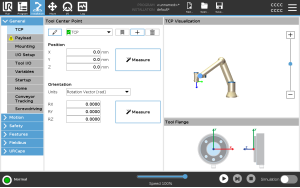
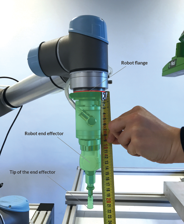
The flange is not always the point you want to control. If the robot holds a gripper, welding torch, vacuum cup, or probe, the important point is the TCP at the working end of the tool. Universal Robots documentation describes a TCP as a point on the tool with translation and rotation relative to the center of the tool output flange; when all TCP values are zero, the TCP coincides with the flange. That maps directly to:
T_base_tcp = T_base_flange * T_flange_tcp
If you want to inspect the TCP in fixture coordinates, invert the user transform:
T_user_tcp = inv(T_base_user) * T_base_tcp
This small equation saves many debugging hours. If T_user_tcp.z() is unexpectedly negative while the robot is physically above the pallet, the user frame Z axis may be flipped. If T_user_tcp is off by exactly the tool length, the TCP offset may be missing or multiplied in the wrong order.
Base, User, Object: Program Relative to Fixtures
Imagine a jig on a table. The user-frame origin is at the front-left corner of the jig, X runs along a row of holes, Y runs across columns, and Z points upward. You want to move the TCP to the third hole:
T_user_target = translate(0.120, 0.040, 0.030) * rotate(...)
The robot, however, accepts the final target in base coordinates:
T_base_target = T_base_user * T_user_target
If the jig later moves 200 mm or rotates 10 degrees on the table, you should not edit every waypoint. You only re-measure T_base_user. This is the practical reason user frames, workobjects, and features exist on industrial pendants.
An object frame adds another layer. A camera or fixture system may return the object pose in the user frame:
T_base_grasp = T_base_user * T_user_object * T_object_grasp
T_object_grasp is usually a fixed offset from the object's reference frame to the desired grasp frame. This separation is clean: perception owns T_user_object, the process engineer adjusts T_object_grasp, and the robot controller only composes transforms.

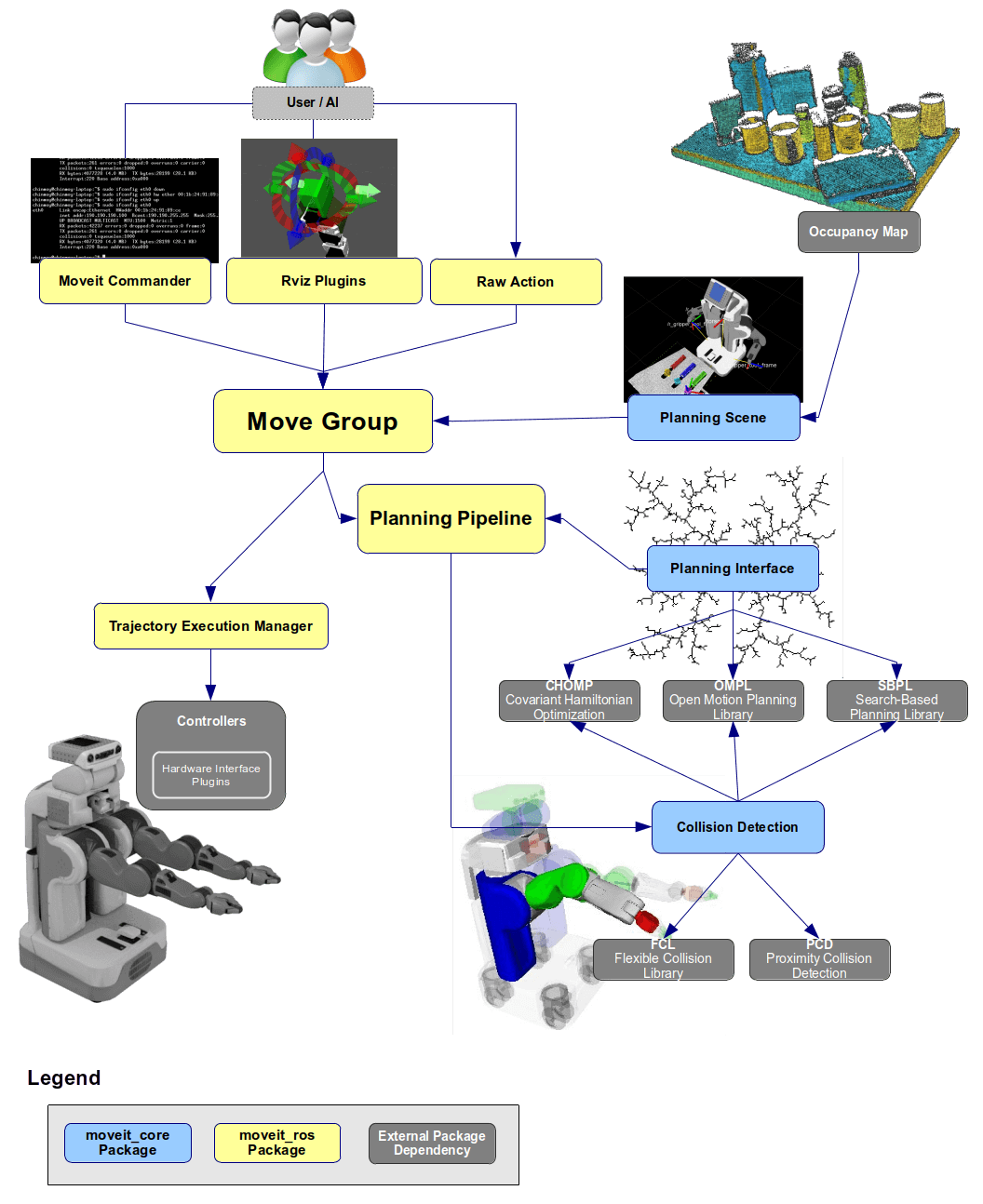
ROS tf2 uses the same mental model: frames form a tree, and the system looks up transforms between frames through that tree. This article does not require ROS, but the engineering rule is identical: every transform needs a parent, a child, a clear name, and, in a real-time system, a timestamp.
Python Prototype with SpatialMath
Install the packages:
python3 -m venv .venv
source .venv/bin/activate
pip install spatialmath-python matplotlib numpy
The following script creates a user frame offset from the base frame, a target in that user frame, a flange pose in base coordinates, and then computes the TCP pose and expresses it back in user coordinates.
# python/frame_demo.py
import numpy as np
from spatialmath import SE3
from spatialmath.base import trprint
import matplotlib.pyplot as plt
def rpy_deg(roll, pitch, yaw):
return SE3.RPY([roll, pitch, yaw], unit="deg", order="xyz")
T_base_user = SE3(0.45, -0.20, 0.08) * rpy_deg(0, 0, 30)
T_user_target = SE3(0.12, 0.04, 0.03) * rpy_deg(180, 0, 90)
T_base_target = T_base_user * T_user_target
T_base_flange = SE3(0.52, -0.08, 0.36) * rpy_deg(180, 0, 45)
T_flange_tcp = SE3(0.0, 0.0, 0.18) * rpy_deg(0, 0, 0)
T_base_tcp = T_base_flange * T_flange_tcp
T_user_tcp = T_base_user.inv() * T_base_tcp
print("T_base_user")
trprint(T_base_user.A, label="base_from_user")
print("\nT_user_target")
trprint(T_user_target.A, label="user_from_target")
print("\nT_base_target = T_base_user * T_user_target")
trprint(T_base_target.A, label="base_from_target")
print("\nT_user_tcp = inv(T_base_user) * T_base_tcp")
trprint(T_user_tcp.A, label="user_from_tcp")
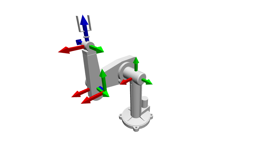
fig = plt.figure()
ax = fig.add_subplot(111, projection="3d")
T_base_user.plot(frame="user", color="blue", length=0.08, ax=ax)
T_base_target.plot(frame="target", color="green", length=0.08, ax=ax)
T_base_flange.plot(frame="flange", color="orange", length=0.08, ax=ax)
T_base_tcp.plot(frame="tcp", color="red", length=0.08, ax=ax)
ax.set_title("Robot frames in base coordinates")
plt.show()
Check these points:
T_base_targetshould change when you rotateT_base_user; the target is not merely shifted along base X/Y.T_base_tcpdiffers fromT_base_flangeby 180 mm along the flange Z axis, not the base Z axis.T_user_tcpis the TCP pose seen from the jig. This value is extremely useful for palletizing, bin picking, and inspection debugging.
A useful habit is to print both the matrix and a compact [x, y, z, r, p, y] representation while prototyping. When you port to C++, unit tests should compare matrices, translations, and orientations with tolerances, not log strings.
C++ Implementation with Eigen::Isometry3d
In the C++/CMake setup article, Eigen became our math foundation. For rigid 3D transforms, Eigen::Isometry3d is a better fit than a raw Matrix4d because it carries the meaning "rotation + translation" and provides inverse(), translation(), and linear().
// include/arm_controller/frame_manager.hpp
#pragma once

#include <Eigen/Geometry>
#include <cmath>
#include <string>
#include <unordered_map>

namespace arm_controller {

using Pose = Eigen::Isometry3d;

inline double deg2rad(double deg) {
    constexpr double pi = 3.14159265358979323846;
    return deg * pi / 180.0;
}

inline Pose makePose(double x, double y, double z,
                     double roll_deg, double pitch_deg, double yaw_deg) {
    const Eigen::AngleAxisd roll(deg2rad(roll_deg), Eigen::Vector3d::UnitX());
    const Eigen::AngleAxisd pitch(deg2rad(pitch_deg), Eigen::Vector3d::UnitY());
    const Eigen::AngleAxisd yaw(deg2rad(yaw_deg), Eigen::Vector3d::UnitZ());

    Pose pose = Pose::Identity();
    pose.linear() = (yaw * pitch * roll).toRotationMatrix();
    pose.translation() = Eigen::Vector3d(x, y, z);
    return pose;
}

inline Pose compose(const Pose& a_from_b, const Pose& b_from_c) {
    return a_from_b * b_from_c;
}

inline Pose inverse(const Pose& a_from_b) {
    return a_from_b.inverse();
}

class FrameManager {
public:
    void setBaseToUser(const std::string& name, const Pose& base_from_user) {
        users_[name] = base_from_user;
    }

    void setTcp(const Pose& flange_from_tcp) {
        flange_from_tcp_ = flange_from_tcp;
    }

    Pose baseTargetFromUserTarget(const std::string& user,
                                  const Pose& user_from_target) const {
        return userFrame(user) * user_from_target;
    }

    Pose baseTcpFromBaseFlange(const Pose& base_from_flange) const {
        return base_from_flange * flange_from_tcp_;
    }

    Pose userTcpFromBaseFlange(const std::string& user,
                               const Pose& base_from_flange) const {
        const Pose base_from_tcp = baseTcpFromBaseFlange(base_from_flange);
        return userFrame(user).inverse() * base_from_tcp;
    }

private:
    const Pose& userFrame(const std::string& name) const {
        return users_.at(name);
    }

    std::unordered_map<std::string, Pose> users_;
    Pose flange_from_tcp_ = Pose::Identity();
};

}  // namespace arm_controller
A minimal demo:
// src/frame_demo.cpp
#include "arm_controller/frame_manager.hpp"

#include <iostream>

int main() {
    using arm_controller::FrameManager;
    using arm_controller::makePose;

    FrameManager frames;
    frames.setBaseToUser("jig_a", makePose(0.45, -0.20, 0.08, 0, 0, 30));
    frames.setTcp(makePose(0.0, 0.0, 0.18, 0, 0, 0));

    const auto user_from_target = makePose(0.12, 0.04, 0.03, 180, 0, 90);
    const auto base_from_target =
        frames.baseTargetFromUserTarget("jig_a", user_from_target);

    const auto base_from_flange = makePose(0.52, -0.08, 0.36, 180, 0, 45);
    const auto user_from_tcp =
        frames.userTcpFromBaseFlange("jig_a", base_from_flange);

    std::cout << "base_from_target:\n" << base_from_target.matrix() << "\n\n";
    std::cout << "user_from_tcp:\n" << user_from_tcp.matrix() << "\n";
    return 0;
}
Minimal CMake:
cmake_minimum_required(VERSION 3.16)
project(arm_controller_frames LANGUAGES CXX)

set(CMAKE_CXX_STANDARD 17)
set(CMAKE_CXX_STANDARD_REQUIRED ON)

find_package(Eigen3 REQUIRED)

add_executable(frame_demo src/frame_demo.cpp)
target_include_directories(frame_demo PRIVATE include)
target_link_libraries(frame_demo PRIVATE Eigen3::Eigen)
Build it:
cmake -S . -B build
cmake --build build
./build/frame_demo
The important detail is that setTcp() stores T_flange_tcp, not T_base_tcp. The TCP is a property of the tool mounted on the flange, so it must not depend on the current joint state. baseTcpFromBaseFlange() is where we compose it with the current flange pose.
Real-Robot Frame Bug Checklist
Before running a real motion command, check these items in order:
- Units: is translation in meters or millimeters? Is orientation in degrees or radians?
- Orientation convention: what RPY order is used? Is the vendor pose actually a rotation vector?
- Names: do variables state parent and child, such as
base_from_userandflange_from_tcp? - TCP offset: is it along the flange axis, not accidentally along the base axis?
- User frame: has it been re-taught after the jig moved?
- Perception target: is it still in camera/object frame? Has camera calibration been applied?
- Before
MoveL, have you logged or plottedT_base_targetand checked that it sits in a reasonable workspace region?
If you work with ROS or ros2_control, also read ROS 2 control hardware interface: the real controller must keep frames consistent across the driver, state publisher, planning scene, and motion command. For larger cells or fleets, Open-RMF fleet management shows the same lesson at system level: the world model and frame conventions must stay consistent.
Conclusion
Frame transforms are a small part of the codebase, but they determine whether the entire robot arm controller is trustworthy. The three equations to remember are:
T_base_target = T_base_user * T_user_target
T_base_tcp    = T_base_flange * T_flange_tcp
T_user_tcp    = inv(T_base_user) * T_base_tcp
When those three lines are named correctly, tested, and plotted, later work on MoveJ, MoveL, blending, jogging, and motion planning becomes much easier to debug. In the MoveJ/MoveL article, the final Cartesian target still has to be expressed in the base frame before the planner or controller executes it.
References
- Universal Robots TCP Configuration
- Pickit: How to define the TCP on Universal Robots
- Eigen Geometry: Space transformations
- Spatial Math Toolbox overview
- ROS 2 tf2 tutorials