In the previous article, we created a clean C++/CMake/Eigen project for the controller. This article adds the first real robotics layer: the robot model. If the model is wrong, everything downstream becomes wrong in subtle ways. Forward kinematics may be off by a few centimeters, inverse kinematics may converge to strange joint values, a MoveL path may look straight in software but bend on the real arm, and tool-frame jogging may move in the opposite direction.
A serial robot arm model has two meanings. The mechanical meaning describes joints, links, joint axes, link lengths, offsets, base frame, flange frame and TCP. The software meaning stores the same information in a form code can compute with: a DH table, homogeneous transforms, a URDF file, or a parsed model from a library such as Robotics Toolbox or Pinocchio. The goal here is practical: by the end, you should be able to fill a UR5 DH table yourself, write a small model in Python/NumPy and C++/Eigen, and know when to use URDF instead.
Joint Space and Cartesian Space
Joint space is the space of joint variables. A UR5 has six revolute joints, so one robot configuration is:
q = [q1, q2, q3, q4, q5, q6]^T
Each qi is normally in radians. When you command MoveJ, the controller mostly plans in joint space: every joint moves from its current angle to its target angle under velocity and acceleration limits. This is robust, easy to constrain, and generally friendly to the robot mechanism. The downside is that the TCP does not move in a straight Cartesian line.
Cartesian space, often called task space, is the pose space of the tool. A 6D pose contains position (x, y, z) and orientation. In classical robotics code, the pose is commonly represented as an element of SE(3): a 4x4 matrix containing a 3x3 rotation and a 3x1 translation. When you command MoveL, the intent is for the TCP to move along a straight line in Cartesian space; the controller then solves IK repeatedly to convert each intermediate pose into joint values.
The two spaces are connected by FK and IK:
q in joint space  --FK-->  T_base_tool in SE(3)
T_base_tool       --IK-->  q, sometimes one of many valid q solutions
A common beginner mistake is to think that "where the robot is" means only q, or only (x, y, z). The joint vector says how the mechanism is folded. The pose says where the TCP is and how it is oriented relative to a reference frame. Many joint configurations can produce the same TCP pose; a single joint configuration produces exactly one pose if the model is correct.
Links, Joints, Base, Flange and TCP
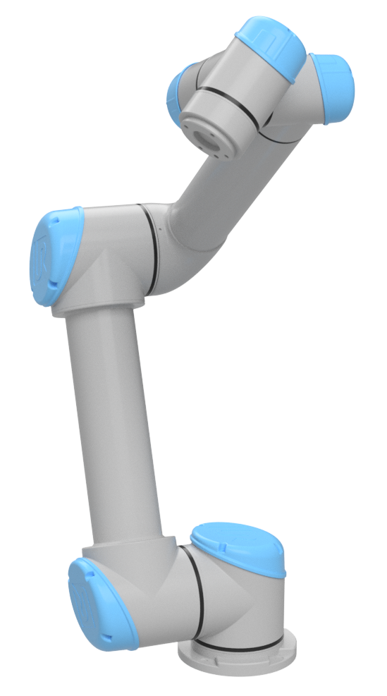
A serial arm is made of rigid links connected by joints. A link is a mechanical body: base, upper arm, forearm, wrist links. A joint is the degree of freedom between two links: a revolute joint rotates around an axis, while a prismatic joint translates along an axis. UR5 has six revolute joints.
In a model, each joint has an axis. In DH notation, the z_i axis is usually aligned with the motion axis of joint i. In URDF, a joint has a parent link, child link, origin and axis; meshes, inertias and collision geometry live in the link/joint tree. URDF is therefore richer than DH, while DH is compact and convenient for serial-arm FK.
Important frames:
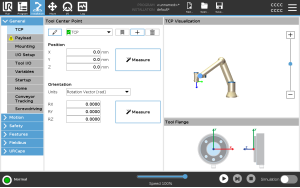
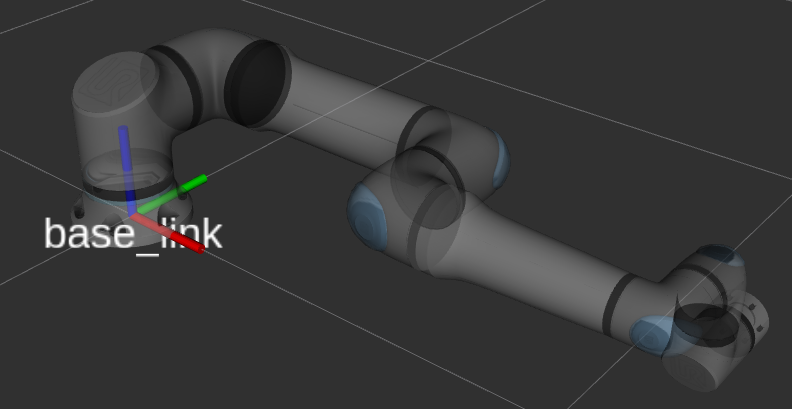
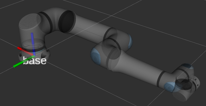
base_link: the root frame of the kinematic tree under ROS conventions. In the Universal Robots ROS 2 documentation,base_linkis the root link and follows REP-103.base: the controller frame used for poses shown on the teach pendant. For UR robots,basehas the same position asbase_linkbut a different orientation.flange: the mechanical mounting interface at the end of the wrist, where a gripper or tool is attached.tool0: the tool frame when the TCP has no configured offset. In the UR ROS model,tool0is the FK tool frame for an all-zero tool.- TCP: the real Tool Center Point of the application, such as a suction cup center, welding tip, or midpoint between gripper fingers. The TCP is usually a fixed transform from
flangeortool0.
When writing a controller, always name the pose you are using: T_base_tool0, T_base_flange or T_base_tcp. Avoid a vague variable called pose in core kinematics. A small frame error can become a large tool-offset error on hardware.
SE(3) and Homogeneous Transforms
In robotics, a 3D rigid-body pose is often written as:
T = [ R  p ]
    [ 0  1 ]
R is a 3x3 rotation matrix and p is a 3x1 translation vector. The set of valid transforms of this form is called SE(3), the special Euclidean group. The important condition is that R must be orthonormal and det(R) = 1. The last row is always [0, 0, 0, 1].
This matrix does three jobs:
- It represents the configuration of one frame relative to another, for example
T_base_tcp. - It changes point coordinates from one frame to another.
- It composes transforms through matrix multiplication.
If T_0_1 is the pose of frame 1 in frame 0, and T_1_2 is the pose of frame 2 in frame 1, then:
T_0_2 = T_0_1 * T_1_2
Forward kinematics for a serial arm is just the product of transforms from base to tool:
T_base_tool = A1(q1) * A2(q2) * A3(q3) * A4(q4) * A5(q5) * A6(q6) * T_flange_tcp
This is why the model matters. If each Ai(qi) is correct, FK is correct. If one sign of alpha is wrong, all downstream frames rotate incorrectly.
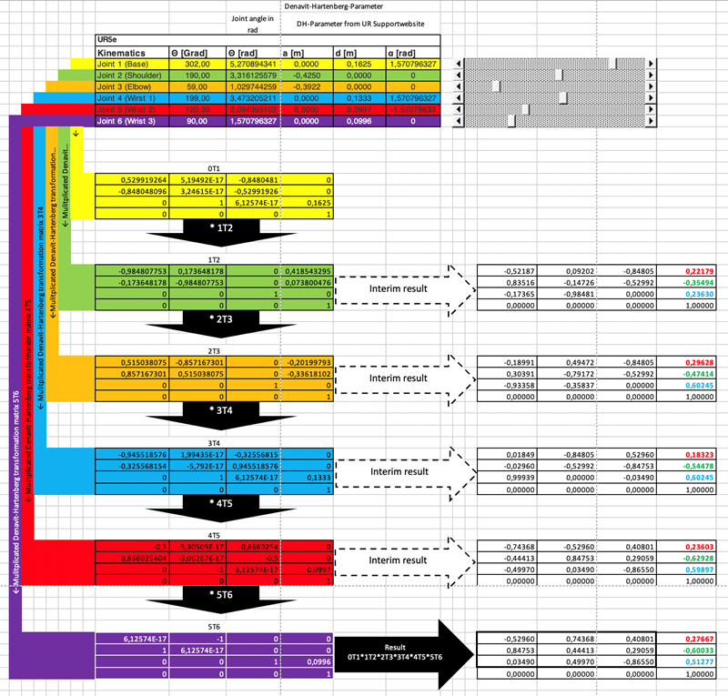
What DH Parameters Mean
Denavit-Hartenberg parameters compress the relation between two consecutive frames into four numbers:
| Parameter | Short meaning |
|---|---|
a |
distance along the x axis between consecutive z axes |
alpha |
twist angle around x from the old z axis to the new z axis |
d |
offset along the z axis |
theta |
rotation around the z axis |
For standard DH, the transform is typically written:
A_i = RotZ(theta_i) * TransZ(d_i) * TransX(a_i) * RotX(alpha_i)
The corresponding matrix is:
[ cosθ  -sinθ cosα   sinθ sinα   a cosθ ]
[ sinθ   cosθ cosα  -cosθ sinα   a sinθ ]
[ 0      sinα        cosα        d      ]
[ 0      0           0           1      ]
Modified DH, often associated with Craig's convention, uses a different transform order and different frame placement. One common form is:
A_i = RotX(alpha_{i-1}) * TransX(a_{i-1}) * RotZ(theta_i) * TransZ(d_i)
Do not mix the two conventions in one project. The numbers may look similar, but FK will not match. Universal Robots publishes a, d, alpha tables for UR models and notes that UR's a parameter corresponds to r in some DH descriptions. In this article we use standard DH for the from-scratch implementation because the matrix is easy to write and inspect.
Filling a UR5 DH Table by Hand
The official Universal Robots table for the classic UR5 gives these geometric values:
| Joint | a [m] |
d [m] |
alpha [rad] |
|---|---|---|---|
| 1 | 0 | 0.089159 | pi/2 |
| 2 | -0.425 | 0 | 0 |
| 3 | -0.39225 | 0 | 0 |
| 4 | 0 | 0.10915 | pi/2 |
| 5 | 0 | 0.09465 | -pi/2 |
| 6 | 0 | 0.0823 | 0 |
Because all six joints are revolute, theta_i is the joint variable:
theta_i = q_i + theta_offset_i
For a minimal model, use zero offsets. On a real robot, the calibration file may contain robot-specific corrections. Do not expect a generic table to give millimeter-level absolute accuracy on every physical arm.
The manual process:
- Draw the robot skeleton in its zero pose. It does not have to be pretty; it only needs to show the six joint axes. On a UR5, joints 2 and 3 are nearly parallel, and the wrist contains three axes that meet near the wrist center.
- Assign
z_ito the axis of jointi. For a revolute joint, positive direction follows the right-hand rule. - Assign
x_ias the common normal fromz_itoz_{i+1}. If the axes intersect,ais zero andx_iis chosen consistently to form a right-handed frame. - Assign
y_i = z_i x x_ito complete a right-handed frame. - Measure
a_i: the signed distance alongx_i. For UR5, the shoulder-to-elbow and elbow-to-wrist links appear as-0.425and-0.39225under the UR convention. - Measure
d_i: the offset alongz_i. The main offsets are at the base and wrist:0.089159,0.10915,0.09465,0.0823. - Measure
alpha_i: the rotation aroundx_ifromz_itoz_{i+1}. UR5 givespi/2,0,0,pi/2,-pi/2,0. - Write
theta_ias a variable. If you must match a specific URDF, add offsets and compare FK at several configurations.
ASCII frame sketch:
base
  z1 up through shoulder yaw
  |
  o---- x1 / common normal to joint 2
       shoulder pitch z2  === upper arm ===  elbow pitch z3
                                      === forearm === wrist1 z4
                                                       wrist2 z5
                                                       wrist3 z6 -> flange/tool0

Standard DH chain:
T_0_6 = A1(q1) A2(q2) A3(q3) A4(q4) A5(q5) A6(q6)
A quick check is to run q = zeros(6) in the NumPy FK below, print T_0_6, and compare it with Robotics Toolbox or a Pinocchio-loaded URDF under the same base/tool convention. If the position is close but the orientation differs by 180 degrees, you may be comparing base_link with base, or flange with tool0.
DH or URDF?
Use DH when you need:
- A clear explanation of FK/IK from first principles.
- Fast computation for a 6-DOF serial chain.
- A small controller that does not need meshes, inertia or collision geometry.
- Easy debugging of each link transform from a numeric table.
Use URDF when you need:
- ROS 2, TF, RViz, MoveIt, Gazebo or Isaac Sim integration.
- A tree with fixed frames, grippers, cameras and force-torque sensors.
- Joint limits, visual meshes, collision meshes and inertias.
- Model loading through Pinocchio, KDL, MoveIt or dynamics libraries.
In a real product, I often keep both levels: a small DH or geometric model for unit-testing core FK, and a URDF for the broader ROS/visualization/planning ecosystem. The important part is to add tests that compare both sources at a few known configurations.
Python from Scratch with NumPy
A minimal Python file:
import numpy as np

UR5_DH = [
    # a, alpha, d, theta_offset
    (0.0,      np.pi / 2, 0.089159, 0.0),
    (-0.425,   0.0,       0.0,      0.0),
    (-0.39225, 0.0,       0.0,      0.0),
    (0.0,      np.pi / 2, 0.10915,  0.0),
    (0.0,     -np.pi / 2, 0.09465,  0.0),
    (0.0,      0.0,       0.0823,   0.0),
]

def dh_standard(a: float, alpha: float, d: float, theta: float) -> np.ndarray:
    ct, st = np.cos(theta), np.sin(theta)
    ca, sa = np.cos(alpha), np.sin(alpha)
    return np.array([
        [ct, -st * ca,  st * sa, a * ct],
        [st,  ct * ca, -ct * sa, a * st],
        [0.0, sa,       ca,      d],
        [0.0, 0.0,      0.0,     1.0],
    ], dtype=float)

def fk(dh_table, q: np.ndarray) -> np.ndarray:
    if len(dh_table) != len(q):
        raise ValueError("DH table and q must have the same length")

    T = np.eye(4)
    for (a, alpha, d, theta_offset), qi in zip(dh_table, q):
        T = T @ dh_standard(a, alpha, d, qi + theta_offset)
    return T

if __name__ == "__main__":
    q = np.zeros(6)
    T = fk(UR5_DH, q)
    np.set_printoptions(precision=6, suppress=True)
    print(T)
Details that matter:
- All angles are in radians.
- The table uses
(a, alpha, d, theta_offset)so the code follows the matrix formula naturally. T = T @ A_imeans transforms are multiplied from left to right under one convention.- Do not use Euler angles inside core FK. Euler angles are fine for UI or logs, but the rotation order is easy to misread.
You can add a TCP offset after the flange:
def transl(x, y, z):
    T = np.eye(4)
    T[:3, 3] = [x, y, z]
    return T

T_flange_tcp = transl(0.0, 0.0, 0.120)
T_base_tcp = fk(UR5_DH, q) @ T_flange_tcp
In the later article on FK, IK and Jacobians, we will reuse this model to compute numerical Jacobians and test IK.
C++ from Scratch with Eigen
In C++, represent a valid rigid pose with Eigen::Isometry3d. Convert to Eigen::Matrix4d when you need to print, serialize or call an API that expects a matrix. Isometry3d makes the intent explicit: rotation plus translation, no scale and no shear.
Example model header:
#pragma once

#include <Eigen/Geometry>
#include <string>
#include <vector>

namespace arm {

enum class JointType {
    Revolute,
    Prismatic,
    Fixed,
};

struct Joint {
    std::string name;
    JointType type{JointType::Revolute};
    double lower{-3.141592653589793};
    double upper{3.141592653589793};
};

struct Link {
    std::string name;
    double a{0.0};
    double alpha{0.0};
    double d{0.0};
    double theta_offset{0.0};
    Joint joint;
};

Eigen::Isometry3d dhStandard(double a, double alpha, double d, double theta);
std::vector<Link> parseDhCsv(const std::string& path);
Eigen::Isometry3d forwardKinematics(const std::vector<Link>& links, const Eigen::VectorXd& q);

}  // namespace arm
Implementation:
#include "arm/model.hpp"

#include <Eigen/Dense>
#include <fstream>
#include <sstream>
#include <stdexcept>

namespace arm {

Eigen::Isometry3d dhStandard(double a, double alpha, double d, double theta) {
    const double ct = std::cos(theta);
    const double st = std::sin(theta);
    const double ca = std::cos(alpha);
    const double sa = std::sin(alpha);

    Eigen::Matrix4d M;
    M << ct, -st * ca,  st * sa, a * ct,
         st,  ct * ca, -ct * sa, a * st,
         0.0, sa,       ca,      d,
         0.0, 0.0,      0.0,     1.0;

    Eigen::Isometry3d T = Eigen::Isometry3d::Identity();
    T.matrix() = M;
    return T;
}

std::vector<Link> parseDhCsv(const std::string& path) {
    std::ifstream file(path);
    if (!file) {
        throw std::runtime_error("Cannot open DH file: " + path);
    }

    std::vector<Link> links;
    std::string line;
    while (std::getline(file, line)) {
        if (line.empty() || line[0] == '#') {
            continue;
        }

        std::stringstream ss(line);
        std::string name, a, alpha, d, theta_offset;
        std::getline(ss, name, ',');
        std::getline(ss, a, ',');
        std::getline(ss, alpha, ',');
        std::getline(ss, d, ',');
        std::getline(ss, theta_offset, ',');

        Link link;
        link.name = name;
        link.a = std::stod(a);
        link.alpha = std::stod(alpha);
        link.d = std::stod(d);
        link.theta_offset = std::stod(theta_offset);
        link.joint.name = name + "_joint";
        links.push_back(link);
    }
    return links;
}

Eigen::Isometry3d forwardKinematics(const std::vector<Link>& links, const Eigen::VectorXd& q) {
    if (static_cast<int>(links.size()) != q.size()) {
        throw std::runtime_error("links.size() must match q.size()");
    }

    Eigen::Isometry3d T = Eigen::Isometry3d::Identity();
    for (int i = 0; i < q.size(); ++i) {
        const Link& link = links[static_cast<std::size_t>(i)];
        T = T * dhStandard(link.a, link.alpha, link.d, q[i] + link.theta_offset);
    }
    return T;
}

}  // namespace arm
UR5 CSV:
# name,a,alpha,d,theta_offset
shoulder_pan,0.0,1.5707963267948966,0.089159,0.0
shoulder_lift,-0.425,0.0,0.0,0.0
elbow,-0.39225,0.0,0.0,0.0
wrist_1,0.0,1.5707963267948966,0.10915,0.0
wrist_2,0.0,-1.5707963267948966,0.09465,0.0
wrist_3,0.0,0.0,0.0823,0.0
Minimal CMake linking Eigen:
cmake_minimum_required(VERSION 3.16)
project(arm_model_demo LANGUAGES CXX)

set(CMAKE_CXX_STANDARD 17)
set(CMAKE_CXX_STANDARD_REQUIRED ON)

find_package(Eigen3 REQUIRED)

add_library(arm_model src/model.cpp)
target_include_directories(arm_model PUBLIC include)
target_link_libraries(arm_model PUBLIC Eigen3::Eigen)

add_executable(demo src/main.cpp)
target_link_libraries(demo PRIVATE arm_model)
Build commands:
cmake -S . -B build -G Ninja
cmake --build build
./build/demo ur5_dh.csv
In main.cpp, print T.matrix() and compare it with Python. If Python and C++ disagree, do not move on to IK. Fix the convention first.
Using Robotics Toolbox for Python
Peter Corke's Robotics Toolbox for Python is very useful as a reference implementation. It provides DH models, URDF models, SE3, trajectories and the Swift visualizer. For UR5, the typical workflow is:
import numpy as np
import roboticstoolbox as rtb

robot = rtb.models.DH.UR5()
q = np.zeros(6)
T = robot.fkine(q)
print(T)

robot.plot(q, backend="swift")
If your installed version does not expose exactly UR5, inspect rtb.models.DH or construct a DHRobot manually from RevoluteDH links. The key is to compare the same convention. Some library models include a default base transform or tool transform, so before deciding your code is wrong, print robot.base, robot.tool and the link table.
Loading URDF with Pinocchio 3.x
Pinocchio is a powerful C++/Python library for kinematics and dynamics. As of the documentation available up to June 2026, the ROS Rolling docs list Pinocchio 3.9.0 as the latest 3.x release line. The basic Python API for loading a URDF is compact:
import pinocchio as pin

urdf_filename = "ur5_robot.urdf"
model = pin.buildModelFromUrdf(urdf_filename)
data = model.createData()

q = pin.neutral(model)
pin.forwardKinematics(model, data, q)

for name, placement in zip(model.names, data.oMi):
    print(name, placement.translation.T)
A Pinocchio model differs from a DH table because it parses the URDF tree: fixed joints, inertial frames, optional visual/collision geometry, and auxiliary frames such as base, flange and tool0. When comparing FK, select the correct frame:
frame_id = model.getFrameId("tool0")
pin.framesForwardKinematics(model, data, q)
T_base_tool0 = data.oMf[frame_id]
print(T_base_tool0.homogeneous)

In an industrial controller, Pinocchio becomes attractive when you need Jacobians, dynamics, centroidal quantities, contacts or branched robots. In this article, we use it mainly as a URDF ground truth so our from-scratch model does not drift away from standard conventions.
Self-Check Before IK
Before moving to IK, answer these questions:
- Is your
qin radians or degrees? - Does Python FK match C++ FK at
q = zeros(6)? - Does it still match at an asymmetric configuration such as
[0.2, -1.1, 1.4, -0.7, 0.5, 0.3]? - Are you comparing
base,base_linkor world? - Are you comparing
flange,tool0or a custom TCP? - Is your table standard DH or modified DH?
- Are there
theta_offsetor calibration corrections being ignored?
If this checklist passes, you have a solid base for IK. In the article on frames and jogging, the base, tool and world frames return from a velocity-control perspective. Outside this series, ROS2 Control Hardware Interface is a useful bridge from robot model to driver-level integration.
References
- Universal Robots DH parameters: classic UR5 and UR5e DH tables.
- Universal Robots ROS 2 robot frames:
base_link,base,flange,tool0. - Modern Robotics on homogeneous transforms: SE(3) and 4x4 matrices.
- Eigen Geometry module:
Transform,Isometry3d, matrix representation. - Robotics Toolbox for Python documentation: DHRobot, URDF models, Swift visualizer.
- Pinocchio Rolling 3.9.0 changelog and loading model example: 3.x version checkpoint,
buildModelFromUrdf,forwardKinematics, model/data workflow.