In Part 3, we agreed on the basic robot-arm model: joints, links, frames and transforms. This article focuses on one thing only: forward kinematics. Given a joint vector q, we compute the tool pose in the base frame:
q = [q1, q2, q3, q4, q5, q6]^T ---> T_base_tool in SE(3)
This is the foundation of a classical controller. MoveJ needs FK to display the current pose. MoveL needs FK to check the TCP path. Tool-frame jogging needs FK to know where the tool axes are pointing. IK in Part 5 goes in the opposite direction, from pose to joints. Jacobians and singularities are intentionally left for Part 6, because packing FK, IK and Jacobians into a single beginner article usually hides the most important issue: conventions.
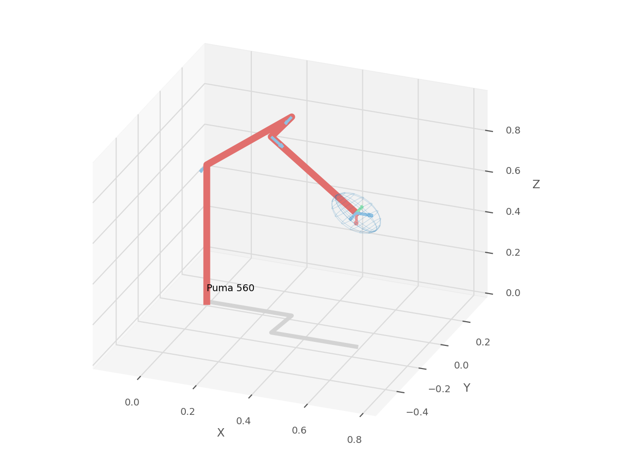
The article has three layers. First, we compute FK by hand for one concrete UR5 configuration. Second, we implement it from scratch in Python and production-style C++/Eigen. Third, we validate the result with real libraries: Robotics Toolbox for Python and Pinocchio 3.x. The DH parameters come from the Universal Robots DH parameters page. Robotics Toolbox documents DHRobot and fkine() in its DH model documentation. For Pinocchio, the important pattern is pin.forwardKinematics() followed by pin.updateFramePlacements(); according to GitHub releases, Pinocchio 3.9.0 is the latest 3.x release before June 13, 2026.
What FK Computes
A 3D rigid-body pose is commonly represented as a 4x4 homogeneous matrix:
T = [ R  p ]
    [ 0  1 ]
R is a 3x3 rotation matrix and p is a 3D translation vector. If R is orthonormal and det(R) = 1, then T belongs to SE(3), the special Euclidean group. In a controller core, avoid returning only (x, y, z, roll, pitch, yaw). Euler angles have multiple conventions and can become singular. Compute FK as SE(3) first; convert to Euler angles, quaternions or axis-angle only at the UI or API boundary.
For a 6-DOF serial arm, FK is just a chain product:
T_0_6 = A_1(q1) * A_2(q2) * A_3(q3) * A_4(q4) * A_5(q5) * A_6(q6)
If a TCP offset exists, append it:
T_base_tcp = T_0_6 * T_flange_tcp
In this article, the TCP is assumed to coincide with the last DH frame, so T_flange_tcp = I. On a real robot, a suction cup, welding tip, camera or gripper needs its own fixed tool transform. Frames and TCP offsets return in the article on frames and jogging.
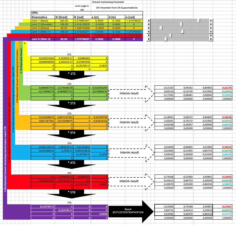
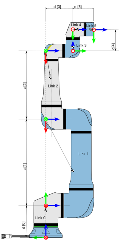
Standard DH for UR5
We use standard DH:
A_i = RotZ(theta_i) * TransZ(d_i) * TransX(a_i) * RotX(alpha_i)
The matrix form is:
A_i =
[ cosθ  -sinθ cosα   sinθ sinα   a cosθ ]
[ sinθ   cosθ cosα  -cosθ sinα   a sinθ ]
[ 0      sinα        cosα        d      ]
[ 0      0           0           1      ]
The nominal UR5 DH table from Universal Robots is:
| Joint | a (m) |
d (m) |
alpha (rad) |
|---|---|---|---|
| 1 | 0 | 0.089159 | pi/2 |
| 2 | -0.425 | 0 | 0 |
| 3 | -0.39225 | 0 | 0 |
| 4 | 0 | 0.10915 | pi/2 |
| 5 | 0 | 0.09465 | -pi/2 |
| 6 | 0 | 0.0823 | 0 |
There are two practical caveats. First, these are nominal parameters, not the factory calibration for your specific arm. A real UR controller uses calibration data to compensate manufacturing deviations. If you need exact agreement with the teach pendant, you must use that calibration. Second, libraries and URDF files may use frame conventions that differ from standard DH. If the result is rotated by 90 degrees or an axis changes sign, inspect the frames before changing the numbers.
Manual FK for One UR5 Configuration
Choose this UR5 joint configuration:
q = [30°, -60°, 90°, -120°, -90°, 45°]
  = [0.523599, -1.047198, 1.570796, -2.094395, -1.570796, 0.785398] rad
Substituting theta_i = q_i into the DH formula gives the six matrices below. Values are rounded to six decimals for readability; tests should use a tolerance around 1e-6.
A1 =
[  0.866025  -0.000000   0.500000   0.000000 ]
[  0.500000   0.000000  -0.866025   0.000000 ]
[  0.000000   1.000000   0.000000   0.089159 ]
[  0.000000   0.000000   0.000000   1.000000 ]

A2 =
[  0.500000   0.866025  -0.000000  -0.212500 ]
[ -0.866025   0.500000  -0.000000   0.368061 ]
[  0.000000   0.000000   1.000000   0.000000 ]
[  0.000000   0.000000   0.000000   1.000000 ]

A3 =
[  0.000000  -1.000000   0.000000  -0.000000 ]
[  1.000000   0.000000  -0.000000  -0.392250 ]
[  0.000000   0.000000   1.000000   0.000000 ]
[  0.000000   0.000000   0.000000   1.000000 ]

A4 =
[ -0.500000   0.000000  -0.866025  -0.000000 ]
[ -0.866025  -0.000000   0.500000  -0.000000 ]
[  0.000000   1.000000   0.000000   0.109150 ]
[  0.000000   0.000000   0.000000   1.000000 ]

A5 =
[  0.000000   0.000000   1.000000   0.000000 ]
[ -1.000000   0.000000   0.000000  -0.000000 ]
[  0.000000  -1.000000   0.000000   0.094650 ]
[  0.000000   0.000000   0.000000   1.000000 ]

A6 =
[  0.707107  -0.707107   0.000000   0.000000 ]
[  0.707107   0.707107  -0.000000   0.000000 ]
[  0.000000   0.000000   1.000000   0.082300 ]
[  0.000000   0.000000   0.000000   1.000000 ]
Now multiply the chain step by step:
T0_2 = A1 * A2 =
[  0.433013   0.750000   0.500000  -0.184030 ]
[  0.250000   0.433013  -0.866025  -0.106250 ]
[ -0.866025   0.500000   0.000000   0.457220 ]
[  0.000000   0.000000   0.000000   1.000000 ]

T0_3 = T0_2 * A3 =
[  0.750000  -0.433013   0.500000  -0.478218 ]
[  0.433013  -0.250000  -0.866025  -0.276099 ]
[  0.500000   0.866025   0.000000   0.261095 ]
[  0.000000   0.000000   0.000000   1.000000 ]

T0_4 = T0_3 * A4 =
[  0.000000   0.500000  -0.866025  -0.423643 ]
[  0.000000  -0.866025  -0.500000  -0.370626 ]
[ -1.000000   0.000000  -0.000000   0.261095 ]
[  0.000000   0.000000   0.000000   1.000000 ]

T0_5 = T0_4 * A5 =
[ -0.500000   0.866025   0.000000  -0.505612 ]
[  0.866025   0.500000  -0.000000  -0.417951 ]
[ -0.000000   0.000000  -1.000000   0.261095 ]
[  0.000000   0.000000   0.000000   1.000000 ]
Finally:
T0_6 = T0_5 * A6 =
[  0.258819   0.965926   0.000000  -0.505612 ]
[  0.965926  -0.258819  -0.000000  -0.417951 ]
[  0.000000   0.000000  -1.000000   0.178795 ]
[  0.000000   0.000000   0.000000   1.000000 ]
The nominal TCP position is:
p = [-0.505612, -0.417951, 0.178795] m
and the orientation is:
R =
[ 0.258819   0.965926   0.000000 ]
[ 0.965926  -0.258819  -0.000000 ]
[ 0.000000   0.000000  -1.000000 ]
You can quickly check that R^T R = I and det(R) = 1. If these fail, you probably mixed transform order, used degrees inside the core, or confused standard DH with modified DH.
Python from Scratch
The Python code below intentionally avoids robotics libraries. We define RotX, RotY, RotZ, Trans, then build DH from them. For beginners, this is better than immediately calling robot.fkine(q), because every transform remains visible.
import numpy as np

def rotx(alpha: float) -> np.ndarray:
    c, s = np.cos(alpha), np.sin(alpha)
    return np.array([
        [1, 0, 0, 0],
        [0, c, -s, 0],
        [0, s, c, 0],
        [0, 0, 0, 1],
    ], dtype=float)

def roty(beta: float) -> np.ndarray:
    c, s = np.cos(beta), np.sin(beta)
    return np.array([
        [c, 0, s, 0],
        [0, 1, 0, 0],
        [-s, 0, c, 0],
        [0, 0, 0, 1],
    ], dtype=float)

def rotz(theta: float) -> np.ndarray:
    c, s = np.cos(theta), np.sin(theta)
    return np.array([
        [c, -s, 0, 0],
        [s, c, 0, 0],
        [0, 0, 1, 0],
        [0, 0, 0, 1],
    ], dtype=float)

def trans(x: float, y: float, z: float) -> np.ndarray:
    T = np.eye(4)
    T[:3, 3] = [x, y, z]
    return T

def dh_standard(a: float, d: float, alpha: float, theta: float) -> np.ndarray:
    return rotz(theta) @ trans(0, 0, d) @ trans(a, 0, 0) @ rotx(alpha)

UR5_DH = [
    (0.0,      0.089159,  np.pi / 2),
    (-0.425,   0.0,       0.0),
    (-0.39225, 0.0,       0.0),
    (0.0,      0.10915,   np.pi / 2),
    (0.0,      0.09465,  -np.pi / 2),
    (0.0,      0.0823,    0.0),
]

def forward_kinematics(q: np.ndarray) -> np.ndarray:
    if q.shape != (6,):
        raise ValueError("UR5 expects q with shape (6,)")

    T = np.eye(4)
    for (a, d, alpha), theta in zip(UR5_DH, q):
        T = T @ dh_standard(a, d, alpha, theta)
    return T

if __name__ == "__main__":
    q = np.deg2rad([30, -60, 90, -120, -90, 45])
    T = forward_kinematics(q)
    np.set_printoptions(precision=6, suppress=True)
    print(T)
Expected output:
[[ 0.258819  0.965926  0.       -0.505612]
 [ 0.965926 -0.258819 -0.       -0.417951]
 [ 0.        0.       -1.        0.178795]
 [ 0.        0.        0.        1.      ]]
Before moving to C++, run this checklist:
| Check | How |
|---|---|
| Radians | np.deg2rad() only at the input boundary |
| Valid rotation | np.allclose(R.T @ R, I) |
| Determinant | np.linalg.det(R) near 1.0 |
| Units | all a, d and p values are meters |
| Multiplication order | T = T @ A_i, not A_i @ T |
Production C++ with Eigen::Isometry3d
In C++, we want a clearer API than a notebook script. A compact structure is DHJoint::transform(theta) plus forwardKinematics(q) returning Eigen::Isometry3d.
// include/arm_kinematics/kinematics.hpp
#pragma once

#include <array>
#include <numbers>
#include <Eigen/Geometry>

namespace arm_kinematics {

struct DHJoint {
  double a;
  double d;
  double alpha;

  Eigen::Isometry3d transform(double theta) const;
};

class UR5Kinematics {
 public:
  Eigen::Isometry3d forwardKinematics(const Eigen::Vector<double, 6>& q) const;

 private:
  static constexpr std::array<DHJoint, 6> dh_ = {{
      {0.0,      0.089159,  std::numbers::pi / 2.0},
      {-0.425,   0.0,       0.0},
      {-0.39225, 0.0,       0.0},
      {0.0,      0.10915,   std::numbers::pi / 2.0},
      {0.0,      0.09465,  -std::numbers::pi / 2.0},
      {0.0,      0.0823,    0.0},
  }};
};

}  // namespace arm_kinematics
// src/kinematics.cpp
#include "arm_kinematics/kinematics.hpp"

#include <cmath>

namespace arm_kinematics {

Eigen::Isometry3d DHJoint::transform(double theta) const {
  const double c = std::cos(theta);
  const double s = std::sin(theta);
  const double ca = std::cos(alpha);
  const double sa = std::sin(alpha);

  Eigen::Matrix4d m;
  m << c, -s * ca,  s * sa, a * c,
       s,  c * ca, -c * sa, a * s,
       0,       sa,      ca,     d,
       0,        0,       0,     1;

  Eigen::Isometry3d T = Eigen::Isometry3d::Identity();
  T.matrix() = m;
  return T;
}

Eigen::Isometry3d UR5Kinematics::forwardKinematics(
    const Eigen::Vector<double, 6>& q) const {
  Eigen::Isometry3d T = Eigen::Isometry3d::Identity();
  for (int i = 0; i < 6; ++i) {
    T = T * dh_[i].transform(q[i]);
  }
  return T;
}

}  // namespace arm_kinematics
Isometry3d is better than exposing a raw Matrix4d because the type communicates intent: this is a rigid transform, not an arbitrary matrix. Inside DHJoint::transform(), the matrix is assigned directly to make the DH convention unambiguous.
CMake and GoogleTest
Minimal CMakeLists.txt:
cmake_minimum_required(VERSION 3.22)
project(arm_fk LANGUAGES CXX)

set(CMAKE_CXX_STANDARD 20)
set(CMAKE_CXX_STANDARD_REQUIRED ON)

find_package(Eigen3 3.4 REQUIRED NO_MODULE)

add_library(arm_kinematics src/kinematics.cpp)
target_include_directories(arm_kinematics PUBLIC include)
target_link_libraries(arm_kinematics PUBLIC Eigen3::Eigen)

include(FetchContent)
FetchContent_Declare(
  googletest
  URL https://github.com/google/googletest/archive/refs/tags/v1.14.0.zip
)
set(gtest_force_shared_crt ON CACHE BOOL "" FORCE)
FetchContent_MakeAvailable(googletest)

enable_testing()

add_executable(fk_test tests/fk_test.cpp)
target_link_libraries(fk_test PRIVATE arm_kinematics GTest::gtest_main)

include(GoogleTest)
gtest_discover_tests(fk_test)
Unit test:
// tests/fk_test.cpp
#include "arm_kinematics/kinematics.hpp"

#include <cmath>
#include <numbers>
#include <gtest/gtest.h>

using arm_kinematics::UR5Kinematics;

TEST(UR5ForwardKinematics, MatchesHandComputedPose) {
  UR5Kinematics fk;

  Eigen::Vector<double, 6> q;
  constexpr double pi = std::numbers::pi;
  q << pi / 6.0, -pi / 3.0, pi / 2.0,
       -2.0 * pi / 3.0, -pi / 2.0, pi / 4.0;

  const Eigen::Isometry3d T = fk.forwardKinematics(q);

  Eigen::Matrix4d expected;
  expected << 0.258819,  0.965926,  0.000000, -0.505612,
              0.965926, -0.258819, -0.000000, -0.417951,
              0.000000,  0.000000, -1.000000,  0.178795,
              0.000000,  0.000000,  0.000000,  1.000000;

  EXPECT_TRUE(T.matrix().isApprox(expected, 1e-6));
}

TEST(UR5ForwardKinematics, RotationIsValid) {
  UR5Kinematics fk;
  Eigen::Vector<double, 6> q;
  q << 0.2, -1.1, 1.4, -0.7, 0.9, -0.3;

  const Eigen::Matrix3d R = fk.forwardKinematics(q).rotation();
  EXPECT_TRUE((R.transpose() * R).isApprox(Eigen::Matrix3d::Identity(), 1e-12));
  EXPECT_NEAR(R.determinant(), 1.0, 1e-12);
}
Build and run:
cmake -S . -B build -DCMAKE_BUILD_TYPE=Release
cmake --build build -j
ctest --test-dir build -V
If the first test fails by a fraction of a millimeter, inspect d1. Some older UR5 packages use 0.08946, while the UR table used here lists 0.089159. A 0.301 mm difference in d1 is enough to move the expected pose.
Validate with Robotics Toolbox
Robotics Toolbox for Python can build a DHRobot from the same table and call fkine(). This is a good validation step because it uses the same standard DH convention but a different implementation.
import numpy as np
from roboticstoolbox import DHRobot, RevoluteDH

ur5 = DHRobot(
    [
        RevoluteDH(d=0.089159, a=0.0,      alpha=np.pi / 2),
        RevoluteDH(d=0.0,      a=-0.425,   alpha=0.0),
        RevoluteDH(d=0.0,      a=-0.39225, alpha=0.0),
        RevoluteDH(d=0.10915,  a=0.0,      alpha=np.pi / 2),
        RevoluteDH(d=0.09465,  a=0.0,      alpha=-np.pi / 2),
        RevoluteDH(d=0.0823,   a=0.0,      alpha=0.0),
    ],
    name="UR5_nominal_UR_DH",
)

q = np.deg2rad([30, -60, 90, -120, -90, 45])
T = ur5.fkine(q).A

expected = np.array([
    [0.258819,  0.965926,  0.0, -0.505612],
    [0.965926, -0.258819,  0.0, -0.417951],
    [0.0,       0.0,      -1.0,  0.178795],
    [0.0,       0.0,       0.0,  1.0],
])

np.testing.assert_allclose(T, expected, atol=1e-6)
print(T)
You can also try rtb.models.DH.UR5(), but print its DH table first. The Robotics Toolbox documentation states that UR5 uses standard DH and SI units, but packaged parameters can be rounded or tied to a specific model revision. For a tutorial, a manually constructed DHRobot keeps every number identical across the article, Python and C++.
Validate with Pinocchio 3.x
Pinocchio is usually introduced through URDF, dynamics, Jacobians and planning stacks. Its FK implementation is production-grade as well. In Pinocchio 3.x, the core pattern is:
pin.forwardKinematics(model, data, q)
pin.updateFramePlacements(model, data)
T = data.oMf[frame_id]
To validate the exact DH table from this article, the snippet below builds a minimal Pinocchio model: every joint is revolute around z, and the fixed segment after each joint is TransZ(d) * TransX(a) * RotX(alpha). The tool0 frame is attached after joint 6.
import numpy as np
import pinocchio as pin

def dh_fixed(a, d, alpha):
    R = pin.rpy.rpyToMatrix(alpha, 0.0, 0.0)  # RotX(alpha)
    p = np.array([a, 0.0, d])
    return pin.SE3(R, p)

dh = [
    (0.0,      0.089159,  np.pi / 2),
    (-0.425,   0.0,       0.0),
    (-0.39225, 0.0,       0.0),
    (0.0,      0.10915,   np.pi / 2),
    (0.0,      0.09465,  -np.pi / 2),
    (0.0,      0.0823,    0.0),
]

model = pin.Model()
parent = 0
joint_ids = []

for i in range(6):
    placement = pin.SE3.Identity() if i == 0 else dh_fixed(*dh[i - 1])
    joint_id = model.addJoint(parent, pin.JointModelRZ(), placement, f"joint_{i + 1}")
    joint_ids.append(joint_id)
    parent = joint_id

tool_frame = pin.Frame(
    "tool0",
    joint_ids[-1],
    0,
    dh_fixed(*dh[-1]),
    pin.FrameType.OP_FRAME,
)
frame_id = model.addFrame(tool_frame)

data = model.createData()
q = np.deg2rad([30, -60, 90, -120, -90, 45])

pin.forwardKinematics(model, data, q)
pin.updateFramePlacements(model, data)
T = data.oMf[frame_id].homogeneous

expected = np.array([
    [0.258819,  0.965926,  0.0, -0.505612],
    [0.965926, -0.258819,  0.0, -0.417951],
    [0.0,       0.0,      -1.0,  0.178795],
    [0.0,       0.0,       0.0,  1.0],
])
np.testing.assert_allclose(T, expected, atol=1e-6)
print(T)
With a real URDF, the code becomes shorter:
import pinocchio as pin
from pinocchio.robot_wrapper import RobotWrapper

robot = RobotWrapper.BuildFromURDF("ur5.urdf", package_dirs=["."])
q = robot.model.neutralConfiguration
pin.forwardKinematics(robot.model, robot.data, q)
pin.updateFramePlacements(robot.model, robot.data)
tool_id = robot.model.getFrameId("tool0")
print(robot.data.oMf[tool_id].homogeneous)
Do not compare a URDF matrix with a DH matrix blindly. UR URDF models often contain base_link, base, flange, tool0, visual frames and collision frames. These are not guaranteed to coincide with the frames you assigned in standard DH. Before declaring either model wrong, print the frame names and draw the frame tree.
Common FK Mistakes
The first mistake is using degrees in the kinematics core. A UI may accept degrees and a teach pendant may display degrees, but the model should receive radians. Convert only at the boundary.
The second mistake is reversing multiplication order. With the convention in this article, write T = T * A_i. If you write T = A_i * T, the final pose belongs to a different robot.
The third mistake is mixing standard DH and modified DH. They share the symbols a, d, alpha and theta, but use different transform order and frame placement. A standard DH table inside a modified DH class can look almost right at one pose and be completely wrong at another.
The fourth mistake is forgetting the tool offset. FK to the flange is not FK to the welding tip. A 150 mm tool makes the error obvious as soon as the wrist rotates.
The final mistake is validating only one pose. One configuration can hide a sign error. Test qz, the pose from this article, and a few random vectors. For random vectors, check the rotation validity and cross-check Python versus C++.
Conclusion
Forward kinematics is not a side formula in a controller. It is the central geometric measurement function: from joint encoder values, the controller knows where the TCP is. If FK is correct, IK, Jacobians, MoveL and jogging have a clean base. If FK is wrong, everything downstream is only compensating for symptoms.
Outside this series, ROS2 Control Hardware Interface shows how kinematics connects to the driver layer, while MoveIt 2 Motion Planning shows how the same geometric model is used for obstacle-aware planning.
The next article solves inverse kinematics: from T_base_tcp back to q, including multiple solutions, joint limits and numerical solvers. After that, the Jacobian gives the velocity relation qdot -> twist, which is the basis for servo jogging and singularity handling.