The previous five articles built a vehicle that can see, knows where it is, and knows what to do. Part 5 ended with an MPC solving in 3 ms and a clean benchmark table. But between "works well in simulation" and "allowed to be sold to real people" lies a gap most software engineers have never had to cross.
That gap has a concrete name: you cannot prove safety by driving.
RAND Corporation's classic study, Driving to Safety (Kalra & Paddock, 2016), worked out the number: to demonstrate with 95% confidence that an autonomous system has a lower fatality rate than human drivers, your fleet would need to accumulate roughly 275 million fatality-free miles — and demonstrating it is 20% better pushes that into the billions. With 100 vehicles running 24/7 at an average 25 mph, 275 million miles takes about 12.5 years. No manufacturer has that patience, and no software version lives that long.
So the automotive industry does not prove safety with raw statistics. It proves safety with structured process: ISO 26262 for component faults, ISO 21448 (SOTIF) for capability limits, and a deliberately chosen scenario set in place of hundreds of millions of random miles.
Series roadmap
- Part 1 — SAE Level 2 vs 2+ vs 3 vs 4: who is responsible for driving, ODD and fallback.
- Part 2 — Sensor fusion: camera, radar and LiDAR building perception that degrades safely.
- Part 3 — Perception: 3D detection, occupancy grids and tracking on nuScenes.
- Part 4 — Localization and HD maps: GNSS/IMU fusion, NDT on LiDAR, map-free approaches.
- Part 5 — Planning and control: from rule-based to MPC and PDM, tracking a real trajectory.
- Part 6 — Validation: ISO 26262, SOTIF and Euro NCAP — proving safety without driving the miles.
ISO 26262 — functional safety: what happens when a component fails
ISO 26262 (current edition 2018, twelve parts) answers a narrow but deep question: if a component in the system fails, how bad can the consequence be, and how rigorous must we therefore be in preventing it?
Note the word "fails". ISO 26262 assumes the system was designed correctly; it worries about bit flips in RAM, burned-out transistors, sensors that stop publishing, CAN frames that get lost. It does not worry about a camera mistaking a white truck for the sky — that belongs to SOTIF, below.
HARA: from hazard to ASIL
The process starts with HARA (Hazard Analysis and Risk Assessment). For each hazardous situation, engineers rate three axes:
| Axis | Meaning | Scale |
|---|---|---|
| S — Severity | How badly someone could be hurt | S0 (no injury) → S3 (life-threatening) |
| E — Exposure | How often that situation occurs | E0 (essentially never) → E4 (very frequent) |
| C — Controllability | Whether an average driver could avoid it | C0 (fully controllable) → C3 (difficult or impossible) |
Those three values index a table yielding the ASIL (Automotive Safety Integrity Level), from QM (ordinary quality management suffices) to ASIL D (the strictest). The ISO 26262-3 table has a neat structure that few references spell out: it is exactly equivalent to adding the indices.
"""Look up the ASIL from the ISO 26262-3 HARA table.
Runs as-is: python3 asil.py
"""

S_LEVELS = {"S0": 0, "S1": 1, "S2": 2, "S3": 3}
E_LEVELS = {"E0": 0, "E1": 1, "E2": 2, "E3": 3, "E4": 4}
C_LEVELS = {"C0": 0, "C1": 1, "C2": 2, "C3": 3}

# Index sum S+E+C: <=6 -> QM, 7 -> A, 8 -> B, 9 -> C, 10 -> D
_BY_SUM = {7: "ASIL A", 8: "ASIL B", 9: "ASIL C", 10: "ASIL D"}

def determine_asil(s: str, e: str, c: str) -> str:
    si, ei, ci = S_LEVELS[s], E_LEVELS[e], C_LEVELS[c]
    # S0 (no injury), E0 (never occurs) or C0 (always controllable) all map to
    # QM by the standard's own definition.
    if si == 0 or ei == 0 or ci == 0:
        return "QM"
    return _BY_SUM.get(si + ei + ci, "QM")

HAZARDS = [
    # (description, S, E, C)
    ("Loss of power steering at highway speed",        "S3", "E4", "C3"),
    ("AEB false brake on the motorway",                "S3", "E3", "C3"),
    ("Lane keeping steers into oncoming traffic",      "S3", "E4", "C2"),
    ("Adaptive cruise fails to slow into a curve",     "S2", "E4", "C1"),
    ("ADAS status indicator on the cluster goes dark", "S0", "E4", "C1"),
]

if __name__ == "__main__":
    for desc, s, e, c in HAZARDS:
        print(f"{determine_asil(s, e, c):>7}  |  {s}/{e}/{c}  |  {desc}")
Output:
 ASIL D  |  S3/E4/C3  |  Loss of power steering at highway speed
 ASIL C  |  S3/E3/C3  |  AEB false brake on the motorway
 ASIL C  |  S3/E4/C2  |  Lane keeping steers into oncoming traffic
 ASIL A  |  S2/E4/C1  |  Adaptive cruise fails to slow into a curve
     QM  |  S0/E4/C1  |  ADAS status indicator on the cluster goes dark
An ASIL is not a label — it is an invoice
The ASIL determines quantitative targets the hardware must meet (ISO 26262-5):
| Target | ASIL B | ASIL C | ASIL D |
|---|---|---|---|
| SPFM — single-point fault metric | ≥ 90% | ≥ 97% | ≥ 99% |
| LFM — latent fault metric | ≥ 60% | ≥ 80% | ≥ 90% |
| PMHF — probabilistic metric for random hardware failures | < 100 FIT | < 100 FIT | < 10 FIT |
1 FIT = 1 failure per 10⁹ operating hours. Below 10 FIT means: if you ran a billion identical ECUs for one hour, fewer than ten of them may fail in a dangerous way. That is why an ASIL D ECU costs several times more than a board with the same raw compute.
Because ASIL D is expensive, the industry uses a sanctioned trick called ASIL decomposition: one ASIL D requirement can be split into two fault-independent ASIL B(D) requirements running on separate channels. The "(D)" records that the origin was D. The make-or-break condition is proving freedom from interference — the two channels must not share power supply, clock, memory, or any common cause of failure. A team that puts two "independent" channels on the same SoC behind the same 5 V rail has decomposed nothing.
ISO 21448 (SOTIF) — when nothing has failed
In 2016, a car with a driver-assistance system engaged struck a white trailer crossing its path in bright sunlight. No component failed. The camera operated to specification, the software ran the code it was given, no bit flipped. The system simply lacked the capability to distinguish a light-colored trailer side from the sky behind it.
ISO 26262 has nothing to say about that. ISO 21448:2022 — Safety Of The Intended Functionality (SOTIF) exists precisely to fill the gap.
The four SOTIF areas
SOTIF partitions the whole scenario space into four areas:
                   SAFE                 HAZARDOUS
             ┌──────────────────┬──────────────────┐
      KNOWN  │   Area 1         │   Area 2         │
             │   known & safe   │   known &        │
             │                  │   hazardous      │
             ├──────────────────┼──────────────────┤
    UNKNOWN  │   Area 4         │   Area 3         │
             │   unknown &      │   unknown &      │
             │   safe           │   hazardous      │
             └──────────────────┴──────────────────┘
All of SOTIF work amounts to shrinking Areas 2 and 3:
- Area 2 → Area 1: the hazardous scenario is known, so fix it — add a sensing modality, tighten the ODD, add a warning, cap the maximum speed.
- Area 3 → Area 2: what is unknown must be found — fleet data mining, scenario fuzzing, large-scale simulation. This is the hard part, because by definition you are searching for something you cannot name yet.
The central concept is the triggering condition — an environmental condition that activates a pre-existing capability limit. Some real examples, not hypotheticals:
| Triggering condition | Limitation activated | Typical SOTIF measure |
|---|---|---|
| Low sun directly ahead at dawn | Camera saturates, contrast lost | Mandatory radar fusion, functional degradation |
| Heavy rain with reflective wet road | LiDAR noise, lane markings vanish | Narrow the ODD using rain-sensor data |
| Truck with scenery painted on its rear | Detector misclassifies | Multi-frame consistency check, prefer radar |
| Traffic sign covered with stickers | Sign recognition errs | Cross-check against the HD map (see Part 4) |
| Work zone with temporary markings over old ones | Lane detector picks the wrong line | Request driver takeover, exit the ODD |
Two standards that complement rather than replace
| ISO 26262 | ISO 21448 (SOTIF) | |
|---|---|---|
| Source of hazard | Component faults | Capability limits + reasonably foreseeable misuse |
| Question | "What if it breaks?" | "What if it works as designed but the design is not enough?" |
| Main tooling | FMEA, FTA, hardware metrics | Scenario analysis, simulation, fleet data |
| Evidence | Quantitative metrics (SPFM/PMHF) | Scenario coverage + residual-risk argument |
An L2+ ADAS system must satisfy both. They answer different questions, and skipping one means skipping half the risk space.
Scenario-based validation: trading 275 million miles for a few thousand scenarios
If you cannot drive enough miles, drive the right ones. Instead of sampling randomly from the real-world distribution — where 99.9% of miles are straight-line cruising on empty road — sample deliberately from the tail.
ASAM OpenSCENARIO: a shared language for scenarios
OpenSCENARIO (ASAM) is an XML format describing what happens on an OpenDRIVE road network (met in Part 4). The root structure of a .xosc file:
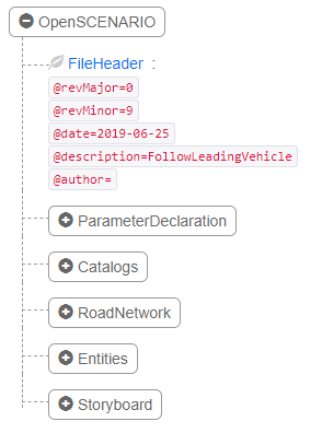
The six root blocks of a .xosc file. RoadNetwork points at the OpenDRIVE map, Entities declares the participating vehicles, Storyboard describes what unfolds. Source: carla-simulator/scenario_runner repo
The valuable part is Storyboard, which separates three things newcomers tend to conflate:
Init— initial state: where each actor starts, at what speed, in what weatherStory→Act→ManeuverGroup→Maneuver→Event— behavior gated by trigger conditions (for example: when the gap to the ego vehicle reaches 40 m, begin the cut-in)StopTrigger— when the scenario ends
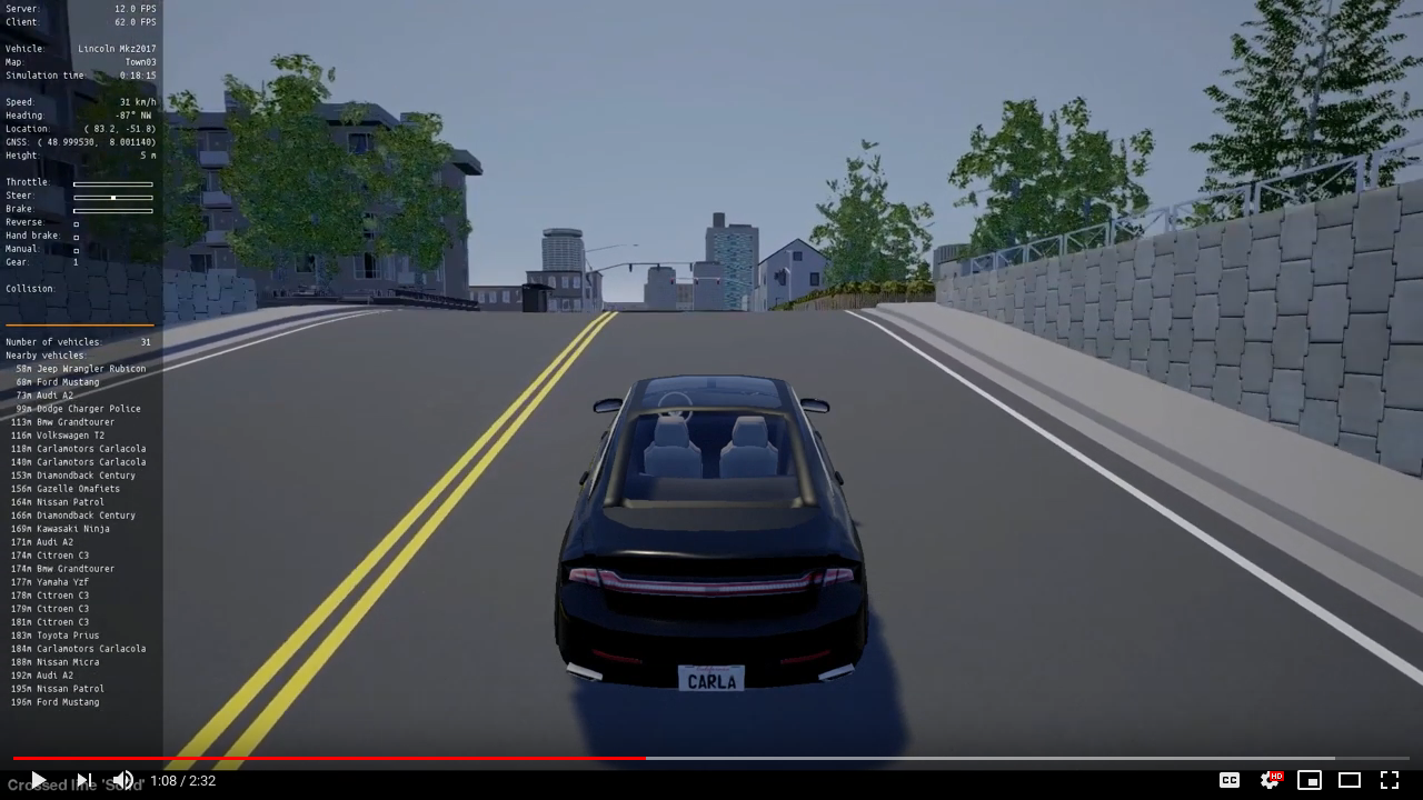
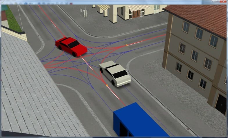
A scenario executed in CARLA with scenario_runner: the left-hand HUD shows speed, GNSS, throttle/brake/steer commands, and nearby vehicles — exactly the quantities used to score pass/fail. Source: carla-simulator/scenario_runner repo
Running a scenario with CARLA scenario_runner:
# Terminal 1 — start the CARLA server
./CarlaUE4.sh -quality-level=Epic

# Terminal 2 — run a cut-in scenario in OpenSCENARIO format
python scenario_runner.py \
  --openscenario srunner/examples/FollowLeadingVehicle.xosc \
  --reloadWorld

# Terminal 3 — drive manually, or attach your own planner
python manual_control.py
Parameter sweeps: where the value actually is
A single scenario is nearly useless. The power comes from sweeping its parameter space — the cut-in vehicle's speed, the gap at which it starts, the duration of the maneuver — and locating the boundary between the safe region and the collision region.
The snippet below does exactly that with a minimal longitudinal model, requiring only NumPy:
"""Sweep cut-in scenario parameters to find the AEB safety boundary.
Longitudinal axis only — enough to show how a scenario grid is scored.
"""
import numpy as np

DT       = 0.02        # 50 Hz simulation step
T_END    = 8.0
A_BRAKE  = -7.0        # maximum braking on dry asphalt (m/s^2)
T_REACT  = 0.35        # system latency: sensor -> detection -> actuator (Part 5)
TTC_TRIGGER = 1.6      # TTC threshold that fires AEB (s)

def simulate(v_ego, v_cut, gap0):
    """Return (minimum gap, minimum TTC). A gap below 0 means a collision."""
    x_ego, x_cut = 0.0, gap0
    v_e, v_c = v_ego, v_cut
    braking_since = None
    min_gap, min_ttc = np.inf, np.inf

    for step in range(int(T_END / DT)):
        t = step * DT
        gap = x_cut - x_ego
        rel_v = v_e - v_c
        ttc = gap / rel_v if rel_v > 0.1 else np.inf

        min_gap = min(min_gap, gap)
        min_ttc = min(min_ttc, ttc)
        if gap <= 0:
            return gap, min_ttc                      # collision

        if braking_since is None and ttc < TTC_TRIGGER:
            braking_since = t                        # AEB decides to brake
        a = A_BRAKE if (braking_since is not None
                        and t >= braking_since + T_REACT) else 0.0

        v_e = max(0.0, v_e + a * DT)
        x_ego += v_e * DT
        x_cut += v_c * DT

    return min_gap, min_ttc

if __name__ == "__main__":
    v_ego = 27.8                                     # 100 km/h
    grid_vcut = np.arange(13.9, 25.0, 2.0)           # 50 -> 90 km/h
    grid_gap  = np.arange(10.0, 45.0, 5.0)

    fails = 0
    total = 0
    print("v_cut(km/h)  gap0(m)   min_gap(m)   result")
    for v_cut in grid_vcut:
        for gap0 in grid_gap:
            min_gap, _ = simulate(v_ego, v_cut, gap0)
            total += 1
            ok = min_gap > 0.0
            fails += (not ok)
            print(f"{v_cut*3.6:9.0f} {gap0:9.0f} {min_gap:12.2f}   "
                  f"{'PASS' if ok else 'COLLISION'}")
    print(f"\nFailure rate: {fails}/{total} = {100*fails/total:.1f}%")
Run it and the boundary appears immediately: with T_REACT = 0.35 s, grid cells combining a small initial gap with a large speed difference land in the collision region. Now change T_REACT to 0.55 — an entirely realistic value if perception slows by 200 ms, per the latency budget in Part 5 — and count the failures again. That is how a software latency requirement becomes a quantified safety requirement, rather than a note reading "should be optimized further".
Where scenarios come from: do not invent them all
Three sources every serious validation program uses:
- Standard catalogs — the Euro NCAP and UN ECE scenario libraries (cut-in, hard braking, pedestrian emerging between parked cars, motorcycle crossing).
- Fleet data mining — scan logs for low-TTC events, hard braking, and sudden driver steering corrections; each one is a real scenario that already happened.
- Automated generation around the boundary — take a failing scenario and perturb its parameters to map the safety boundary precisely. This is the most efficient way to push SOTIF Area 3 into Area 2.
The regulatory frame: UN R157 and the Euro NCAP 2026 protocols
UN R157 — the legal door for Level 3
UN Regulation R157 on ALKS (Automated Lane Keeping Systems) was the first international instrument permitting a Level 3 system on public roads. The original text, in force from early 2021, capped operation at 60 km/h on divided roads with no lane changes. The 01 series of amendments raised the ceiling to 130 km/h and permitted automated lane changes — which is why commercial L3 systems appeared in Europe and Japan in exactly that window.
The key point for engineers: R157 does not only demand good driving. It demands a Data Storage System for Automated Driving (DSSAD) — a black box logging every activation, every takeover request, and every transfer of control. If you do not design that logging in from the start, you will be rewriting architecture at approval time.
Euro NCAP 2026 — the largest revision since 2009
From 2026, Euro NCAP replaces its scoring scheme entirely. The four old boxes (adult occupant, child occupant, vulnerable road users, safety assist) give way to four pillars derived from the Haddon matrix — organized by the stage of a crash rather than by who is affected:
| Pillar | What it assesses | Related series part |
|---|---|---|
| Safe Driving | Technologies for a safer drive: driver state monitoring, quality of human–machine interaction | Part 1 (responsibility, ODD) |
| Crash Avoidance | Systems that prevent or mitigate a crash: AEB, lane support, ISA | Parts 2, 3, 5 |
| Crash Protection | Passive protection: body structure, seatbelts, airbags, pedestrian protection | Outside this series |
| Post-Crash Safety | The "golden hour" after impact: eCall, rescue information | Outside this series |
Each pillar is scored out of 100 points, expressed as a percentage, and the overall star rating is gated by minimum thresholds within each pillar — meaning points cannot be traded across pillars. A car with an excellent body structure but weak ADAS will not reach five stars.
Three concrete changes matter most to an ADAS team:
- ISA is verified on real roads. The accuracy of speed-limit information moves off the test track into actual on-road driving for the first time. Your sign recognition and map cross-check pipeline must now be right on roads you do not get to choose in advance.
- Driver monitoring becomes a prerequisite for five stars. Continuous eye and head tracking is required at the top rating, alongside credit for systems that detect signs of alcohol or drug impairment and for "unresponsive driver" interventions that bring the vehicle safely to a stop when a medical emergency is detected.
- Physical buttons are back. Indicators, hazard lights, wipers, horn, and SOS/eCall must have dedicated physical controls to reach the top rating. That is a direct strike against consolidating everything into a touchscreen, and a reminder that safety includes the user interface, not only the algorithms.
Putting it together: a V-model for an ADAS team
In practice these three layers form a single V-model, and the important property is that every box on the left has exactly one counterpart on the right:
Vehicle-level requirements (ODD, Part 1)  ────►  Vehicle-level testing (Euro NCAP, road)
   │                                                          ▲
   ├─ HARA → ASIL levels                       ASIL validation (fault injection)
   │                                                          ▲
   ├─ SOTIF analysis → triggering conditions   Scenario sweeps (OpenSCENARIO, HIL)
   │                                                          ▲
   ├─ Software architecture (Parts 3–5)        Integration tests (SIL, replayed logs)
   │                                                          ▲
   └─ Module design                            Unit tests + static analysis (MISRA C)
Three mistakes software teams moving into automotive commonly make:
- Treating SOTIF as "a few more test cases". SOTIF is an argument about residual risk, requiring scenario-coverage evidence and acceptance criteria defined up front, not a test suite bolted on after the code is written.
- Ignoring reasonably foreseeable misuse. A driver resting a leg on the wheel to defeat the hands-on sensor is not out of scope — ISO 21448 places it squarely in scope, and Euro NCAP 2026 scores exactly this.
- Designing logging last. R157's DSSAD and the ability to replay a fault in simulation both require consistently timestamped data across every module. Retrofitting that at the end of a program always costs several times more than designing it in.
Series summary
These six articles have traced a complete loop: from reading automation labels correctly, through sensing, perception, localization, and planning, to proving that all of it is safe.
- Safety cannot be proven by mileage — 275 million fatality-free miles is the statistical price, and nobody can pay it.
- ISO 26262 handles component faults, converting risk into an ASIL and then into quantitative hardware targets such as PMHF < 10 FIT.
- ISO 21448 (SOTIF) handles what ISO 26262 never touches: a system operating exactly as designed, where the design was not sufficient for the situation encountered.
- Scenario-based testing replaces random miles with deliberate scenarios, and parameter sweeps are where engineering requirements become measurable safety boundaries.
- Euro NCAP 2026 shifts the focus onto the four stages of a crash, bringing driver monitoring — and even physical buttons — into scope.
The most worthwhile reflection from the whole series: the hard part of autonomous driving is not making it work. Part 5 showed that a simple rule set can beat a sophisticated network in closed-loop; this article shows that most of the effort in a real ADAS program goes into proving rather than building. That is the widest gap between an impressive demo and a product allowed to carry people.