In Part 1 of this series, we explored why 2D RGB images alone aren't enough for reliable robot arm manipulation: depth ambiguity, lack of metric scale, no knowledge of where objects sit in 3D space. The natural follow-up question: how can a robot "see" 3D geometry from an ordinary RGB camera, in real time, with enough accuracy for manipulation?
This article analyzes Robo3R — a feed-forward 3D reconstruction method presented at RSS 2026 — and explains why it's changing how we build perception pipelines for robot arms.
What Is Robo3R and Why Is It Different?
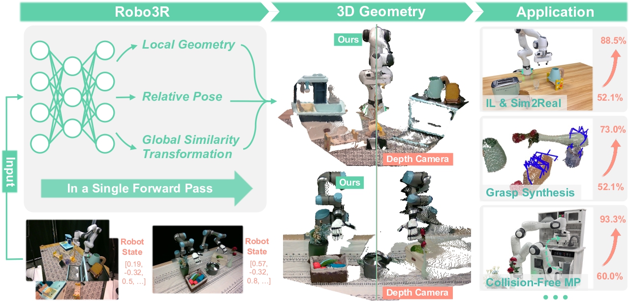
Robo3R stands for Robot 3D Reconstruction. It is designed to solve one specific problem: given RGB images (from one or two cameras) and current robot state, reconstruct a metric-scale 3D geometry of the scene in the robot frame — in real time.
Paper: Robo3R: Enhancing Robotic Manipulation with Accurate Feed-Forward 3D Reconstruction — Sizhe Yang, Linning Xu, Hao Li, Juncheng Mu, Jia Zeng, Dahua Lin, Jiangmiao Pang — RSS 2026, Shanghai AI Laboratory / CUHK / USTC / Tsinghua.
The most important thing to understand upfront: Robo3R is not SLAM, not NeRF, not traditional multi-view stereo. It is a feed-forward model — meaning it runs one forward pass through a neural network and immediately outputs the result, with no iterative optimization loop.
Real-World Speed
- 43.5 Hz with single-view (monocular)
- 18.7 Hz with binocular (stereo)
Fast enough to run inside a robot arm's control loop (typically 20–50 Hz).
Why SLAM and Traditional Multi-View Methods Fall Short
Before diving into Robo3R, it's worth understanding why existing approaches struggle with robot manipulation:
| Method | Problem for Manipulation |
|---|---|
| SLAM (ORB-SLAM, LIO-SAM) | Error drift over time; needs sufficient parallax for camera motion; monocular SLAM doesn't recover metric scale |
| Multi-view stereo (COLMAP) | Offline, not real-time; requires many images from different viewpoints; can't run in a control loop |
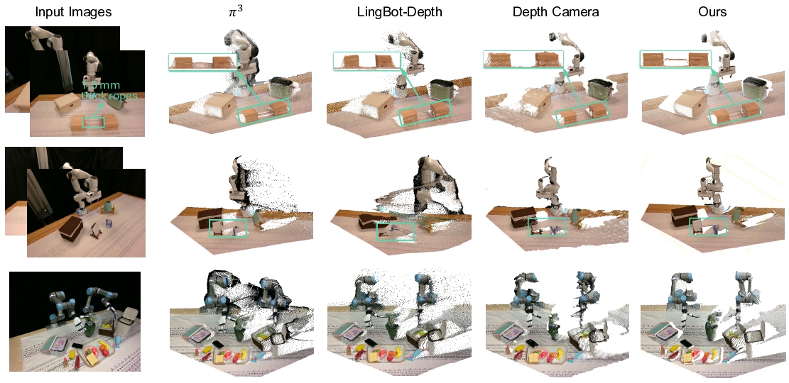
| Depth camera (RealSense, Azure Kinect) | Fails on transparent objects (glass, bottles), reflective surfaces (metal), or very thin objects (<5mm); affected by strong ambient light |
| Monocular depth estimation (MiDaS, Depth Anything) | Outputs scale-relative depth, not metric — robot doesn't know if an object is 3cm or 30cm away |
Real-world example: Unitree G1 needs to insert a screw into a 2mm-tolerance hole. With a depth camera, measurement error on small thin objects can reach 5–10mm — larger than the hole itself. Monocular depth gives a relative value with no absolute scale. Both fail for this task.
Feed-Forward 3D Reconstruction: How It Works
Robo3R is built around four main components that execute as a feed-forward pipeline:
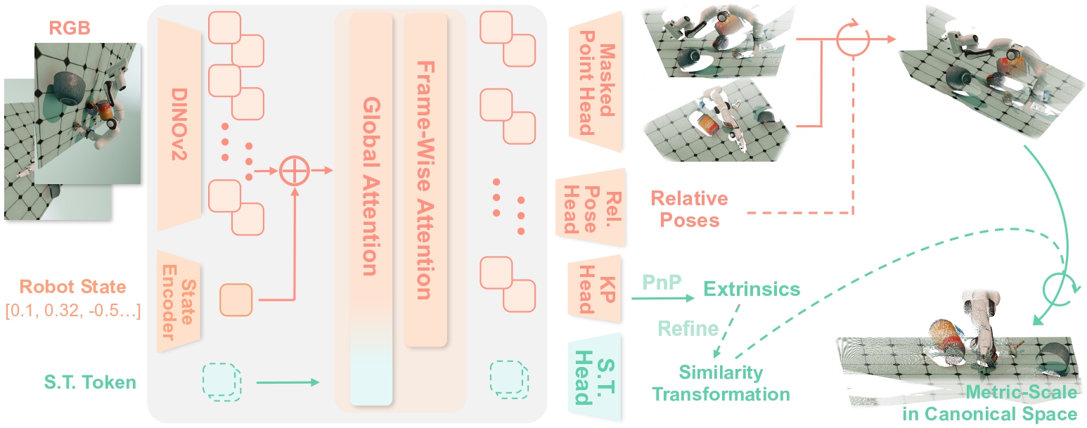
1. Transformer Backbone with Alternating Attention
Input: RGB image(s) from one or more cameras + robot state (joint angles, end-effector pose).
The model uses a transformer backbone with an alternating attention mechanism that interleaves:
- Global attention: processes the whole image to build scene-level context
- Frame-wise attention: focuses on individual frames to capture local features
This design lets the model simultaneously understand the overall scene and preserve fine-grained local details critical for manipulation (object edges, grasp keypoints).
2. Joint Estimation of Local Geometry and Camera Pose
This is a key differentiator: Robo3R jointly estimates:
- Scale-invariant local geometry: surface shape, normals, relative depth of each point
- Relative camera poses: where each camera sits relative to the others (multi-view) or relative to the robot base
In traditional SLAM, these two steps are separate and circularly dependent on each other. Robo3R learns both simultaneously in a single forward pass.
3. Global Alignment into the Robot Frame
After extracting local geometry from multiple frames, the model performs a learned global similarity transformation to:
- Merge all geometry into one unified coordinate system
- Canonical robot frame: a coordinate frame fixed at the robot's base (analogous to
/base_linkin ROS) - Critically: this transformation is learned from data, not manually calibrated
Result: a 3D point cloud in the robot frame, ready for collision checking, grasp planning, and policy input.
4. Masked Point Head — The Key Technical Detail
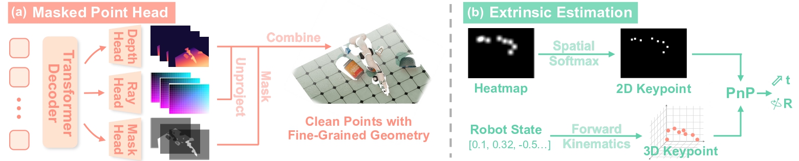
To handle thin and small objects (the biggest weakness of depth sensors), Robo3R uses a masked point head — a specialized prediction head that decomposes output into three components:
Each pixel → [depth d, normalized coordinates (nx, ny), mask m]
           ↓
d × [nx, ny, 1]  →  3D point in local frame
mask m          →  foreground (object) vs. background
A keypoint-based Perspective-n-Point (PnP) formulation then refines camera extrinsics and global alignment, boosting accuracy especially for small objects.
What Is the Canonical Robot Frame and Why Does It Matter?
This is the central concept in Robo3R that beginners often overlook.
The Problem with Arbitrary Frames
When a robot moves, the camera mounted on its arm moves with it. If you build a 3D map in an arbitrary "camera frame" or "world frame," every time the robot moves you have to retransform the entire map. For manipulation, the arm specifically needs to know object positions relative to itself, not relative to the external world.
Canonical Robot Frame Defined
The canonical robot frame is a coordinate system fixed at the robot's base:
- Origin: center of the robot base (or
/base_link) - Z-axis: pointing upward
- X-axis: pointing forward
- Does not change when the gripper or arm moves
When Robo3R reconstructs the 3D scene in the canonical robot frame, the downstream policy can:
- Use 3D coordinates directly to compute gripper trajectories
- Avoid complex transforms between camera frame and robot frame
- Directly compare object positions with robot kinematic state
Think of it like always viewing a map oriented to North — regardless of which direction you're facing, every coordinate stays consistent and easy to reason about.
Metric Scale — Why 0.007 Matters
Robo3R achieves a scale error of 0.007 (fractional metric error). Competing methods typically show scale error > 0.46.
What this means in practice: at a distance of 30cm, a scale error of 0.007 corresponds to ~2mm — within acceptable tolerance for most manipulation tasks. A scale error of 0.46 corresponds to ~14cm — useless for precise grasping.
scale_error = |d_predicted - d_ground_truth| / d_ground_truth

Robo3R:       0.007  →  at d=30cm, error ≈ 2mm   ✓
Competitors:  0.46+  →  at d=30cm, error ≈ 14cm  ✗
Robo3R-4M: The Dataset Behind the Model
The model can't learn metric scale from nothing — it needs synthetic data with ground-truth 3D. The authors built Robo3R-4M:
| Parameter | Value |
|---|---|
| Total frames | 4 million |
| Number of scenes | 120,000 |
| Object assets | 16,911 (DTC + Objaverse) |
| Textures | 4,710 |
| Environment maps | 6,512 (diverse lighting) |
| Robot | Franka FR3 (NVIDIA Isaac Sim) |
| Modalities | RGB, depth, semantic masks, robot states, camera intrinsics/extrinsics |
Two subsets:
- 100k scenes: objects randomly placed on tabletop (general scenes)
- 20k scenes: one object grasped by gripper, others on tabletop (grasping scenarios)
What makes this dataset special: the deliberate inclusion of transparent, reflective, and thin-shaped objects — exactly the materials that real depth cameras can't handle.
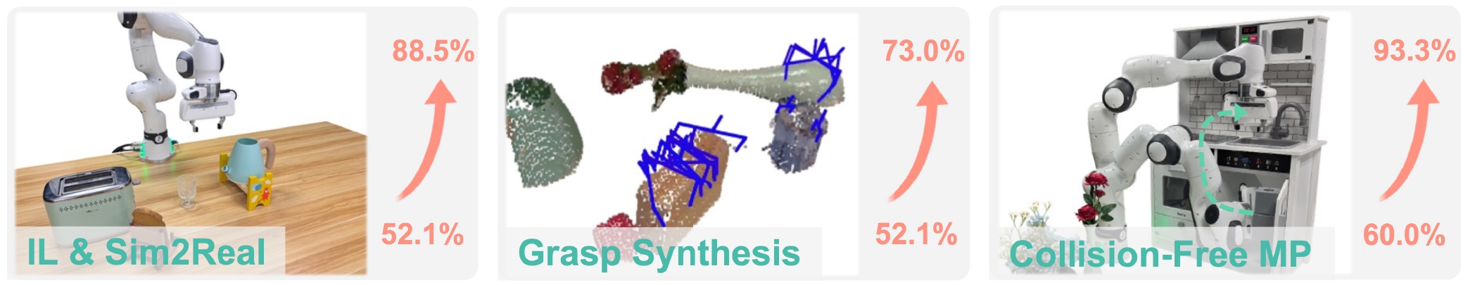
Results: Numbers That Matter
Imitation Learning (16 trials per task)
| Task | Robo3R | Depth Camera | Improvement |
|---|---|---|---|
| Sweep Bean | 14/16 (87.5%) | 4/16 (25%) | +62.5% |
| Insert Screw | 15/16 (93.8%) | 7/16 (43.8%) | +50% |
| Breakfast | 12/16 (75%) | 11/16 (68.8%) | +6.2% |
| BiDex Pour | 16/16 (100%) | 16/16 (100%) | 0% |
Insert Screw is the hardest task: a 2mm hole requiring sub-millimeter accuracy. Robo3R achieves 93.8% vs. depth camera's 43.8% — nearly double the success rate.
Sim-to-Real Transfer
| Task | Robo3R | Depth Camera |
|---|---|---|
| Push Cube | 16/16 (100%) | 7/16 (43.8%) |
| Pick Cube | 12/16 (75%) | 5/16 (31.3%) |
The sim2real improvement is especially striking because depth cameras suffer from domain gap (different noise patterns and lighting between simulation and reality). Robo3R, learning from RGB, is less affected by sensor noise characteristics.
Collision-Free Motion Planning (Thin Objects)
| Method | Success (5 trials) |
|---|---|
| Robo3R | 5/5 (100%) |
| Depth Camera | 2/5 (40%) |
Depth cameras miss points on thin surfaces — the robot collides. Robo3R reconstructs complete point clouds even for objects as thin as ~1.5mm.
Connection to SPEAR-1: When 3D Perception Meets VLA
Robo3R addresses perception — how to reconstruct 3D from RGB. But what does this 3D perception do for policy/VLA learning?
The answer comes from SPEAR-1 (Scaling Beyond Robot Demonstrations via 3D Understanding):
Paper: SPEAR-1: Scaling Beyond Robot Demonstrations via 3D Understanding — Nikolay Nikolov et al. — CVPR 2026, INSAIT Sofia University.
SPEAR-1 demonstrates that if you pretrain a VLM with 3D understanding capabilities (3D bounding box estimation, object distance, spatial relationships) before fine-tuning it as a VLA, the model learns manipulation far more efficiently:
- 20× less robot data than π0.5 to reach equivalent performance
- 57.3% success rate on the SIMPLER benchmark vs. SpatialVLA's 42.7% and OpenVLA's 1.0%
- Operates zero-shot in environments never seen during training
Mechanism: SPEAR-1 extends PaliGemma (SigLIP + Gemma) with a MoGe monocular depth encoder and 1,024 specialized 3D tokens, enabling the model to reason about 3D space directly through language.
What Robo3R and SPEAR-1 Share
Both confirm the same principle: 3D understanding is a non-negotiable foundation for manipulation policy.
- Robo3R: provides accurate 3D geometry as policy input (point cloud in robot frame)
- SPEAR-1: integrates 3D understanding directly into the VLM/VLA backbone
The two approaches are complementary — you could use Robo3R to reconstruct the scene, then use a SPEAR-1-style VLA to generate actions.
Practical Pipeline: Robo3R in a Real Manipulation System
For Unitree G1 or any robot arm, here's how Robo3R fits into the full system:
┌─────────────────────────────────────────────────────┐
│                  PERCEPTION LAYER                    │
│                                                      │
│  RGB Camera(s)  ──┐                                  │
│  Robot State    ──┤──► Robo3R ──► 3D Point Cloud    │
│  (joint angles) ──┘             (canonical frame)   │
└──────────────────────────┬──────────────────────────┘
                           │
                    ┌──────▼──────┐
                    │   USAGE     │
                    └──────┬──────┘
          ┌────────────────┼────────────────┐
          ▼                ▼                ▼
   Imitation       Grasp Planning    Collision-Free
   Learning        (GraspNet,        Motion Planning
   (DP3, ACT)      AnyGrasp)         (MoveIt2)
Replacing a Depth Sensor with Robo3R
Before Robo3R:
# Old pipeline — depends on depth camera
rgb_image = camera.get_rgb()
depth_map = depth_camera.get_depth()  # fails on transparent objects
point_cloud = backproject(rgb_image, depth_map, intrinsics)
point_cloud_robot = transform(point_cloud, camera_to_robot_tf)
With Robo3R:
# New pipeline — only RGB + robot state
rgb_image = camera.get_rgb()
robot_state = robot.get_joint_angles()
point_cloud_robot = robo3r.infer(rgb_image, robot_state)
# Already in canonical robot frame, already metric-scale
# No depth camera, no complex camera-robot calibration
Limitations and Open Problems
Robo3R isn't a silver bullet. Key limitations to be aware of:
-
Trained on Franka FR3: The dataset primarily uses Franka. For other robots (Unitree G1, UR5, KUKA), fine-tuning or regenerating equivalent data is needed. Robo3R-4M provides the pipeline to do this, but it still requires effort.
-
Single robot morphology in dataset: All 120k scenes use Franka. Generalization to different arm morphologies hasn't been widely tested.
-
Synthetic-to-real gap remains: Despite strong real-world results, the model trains entirely on synthetic data (Isaac Sim). In unusual environments (extreme lighting, materials not represented in the dataset), performance may degrade.
-
Not tested on dynamic scenes: When objects move rapidly (conveyor belts, human handoffs), 18–43 Hz may not be fast enough for accurate tracking.
Summary: What Foundation Does Robo3R Lay?
Robo3R solves a fundamental problem: giving robots accurate metric 3D vision from ordinary cameras. No expensive depth sensor, no complex SLAM, no offline processing — just RGB + robot state, running real-time, producing a reliable point cloud in the robot frame.
This is the perception foundation that all higher layers (grasp planning, policy, VLA) depend on. Just as a carpenter needs precise measurements before placing a beam, a robot needs to know where objects are in 3D space before planning any action.
In Part 3, we'll go deeper: given a 3D point cloud, how does Diffusion Policy 3D (DP3) use it to train a visuomotor policy that dramatically outperforms RGB-only baselines?
Related Posts
- Part 1: Why 2D VLA Isn't Enough for Manipulation — Motivation and full series overview
- Part 3: DP3 — Diffusion Policy 3D with Point Cloud — Using 3D geometry for visuomotor policy
- Part 5: WholeBodyVLA + RL for Humanoid — Whole-body loco-manipulation with latent VLA