The first four posts all used the same data source: real G1 hardware through ROS2. This final post opens a different debugging dimension — comparing simulation and hardware in parallel within the same PlotJuggler session.
Scenario: you train a locomotion policy on MuJoCo, deploy it on real G1, and the robot starts falling at a specific gait phase. What's the cause? Did the sim learn the right behavior but transfer incorrectly (sim2real gap)? Or was the policy never correct — the sim was just too forgiving?
To answer that, you need to see sim state and real state on the same timeline. PlotJuggler's ZMQ Subscriber combined with VideoViewer makes this possible.
Series Roadmap
| # | Post | Content |
|---|---|---|
| 1 | Setup & live connection | Install PlotJuggler, CycloneDDS, subscribe to /lowstate |
| 2 | 23-joint layout + MCAP | Multi-panel layout, MCAP files, phase portraits |
| 3 | IMU debug + FFT | Quaternion → Euler, FFT vibration, Moving Average foot_force |
| 4 | Lua Transforms | Reactive Script for power, tracking error, derived signals |
| 5 | ZMQ + video sim2real (this post) | ZMQ bridge from MuJoCo, VideoViewer sync, sim vs real comparison |
Why Direct Sim-to-Real Comparison?
The gap between simulation and reality is the number one problem in every robot locomotion project. But "gap" is not uniform — it can come from many sources:
Gap Type          Manifestation                         How to Detect
──────────────────────────────────────────────────────────────────────
Dynamics gap      Sim falls faster, real falls slower   Compare angular velocity
Friction gap      Real joint slips at high speed         Tracking error diverges
Timing gap        Gait phase offset → policy transfers wrong  Cross-correlate foot contact
Sensor gap        Real IMU much noisier than sim          FFT noise floor differs
Actuator gap      Real torque lower than sim model        Power curve offset
Looking at this list, it's clear you need quantitative comparison, not "deploy and see if it falls." PlotJuggler with ZMQ + VideoViewer lets you see the gap per channel, per millisecond.
Overall Architecture
┌─────────────────────────┐      ZMQ PUB      ┌──────────────────────┐
│  MuJoCo Simulation      │ ─────────────────▶ │                      │
│  (Python)               │  JSON @ 200 Hz     │  PlotJuggler         │
│  ─ G1 model (MJCF)      │                    │                      │
│  ─ Policy runner        │                    │  ZMQ Subscriber      │
│  ─ zmq_publisher.py     │                    │  ├── sim/* channels  │
└─────────────────────────┘                    │                      │
                                               │  ROS2 Subscriber     │
┌─────────────────────────┐      ROS2          │  ├── /lowstate/*     │
│  G1 Robot (hardware)    │ ─────────────────▶ │                      │
│  ─ SDK real-time        │  /lowstate @ 50Hz  │  VideoViewer         │
│  ─ ROS2 bridge          │                    │  ├── camera_real.mp4 │
└─────────────────────────┘                    │  └── camera_sim.mp4  │
                                               └──────────────────────┘
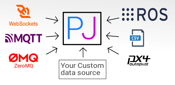
Two data sources run in parallel: ROS2 topics from G1 hardware (set up in part 1), and a ZMQ stream from a MuJoCo Python script. PlotJuggler receives both, displaying them on the same timeline with synchronized timestamps.
Part 1: ZMQ Publisher in Python/MuJoCo
Install the required libraries:
pip install pyzmq mujoco
zmq_publisher.py script — runs alongside the simulation loop:
import zmq
import json
import time
import numpy as np
import mujoco
import mujoco.viewer

# ── ZMQ Setup ────────────────────────────────────────────────────────
context = zmq.Context()
socket  = context.socket(zmq.PUB)
socket.bind("tcp://127.0.0.1:9872")  # PlotJuggler connects to this port

# ── MuJoCo Setup ─────────────────────────────────────────────────────
model = mujoco.MjModel.from_xml_path("unitree_g1/scene.mjcf")
data  = mujoco.MjData(model)

JOINT_NAMES = [
    "left_hip_yaw",   "left_hip_roll",   "left_hip_pitch",
    "left_knee",      "left_ankle_pitch", "left_ankle_roll",
    "right_hip_yaw",  "right_hip_roll",  "right_hip_pitch",
    "right_knee",     "right_ankle_pitch","right_ankle_roll",
    # ... all 23 joints
]

PUBLISH_RATE = 200   # Hz — higher than ROS2 bridge (50Hz) for more resolution
dt_publish   = 1.0 / PUBLISH_RATE
t_last_pub   = 0.0

def get_joint_index(name: str) -> int:
    return mujoco.mj_name2id(model, mujoco.mjtObj.mjOBJ_JOINT, name)

# ── Simulation Loop ───────────────────────────────────────────────────
with mujoco.viewer.launch_passive(model, data) as viewer:
    while viewer.is_running():
        mujoco.mj_step(model, data)

        t_now = data.time
        if t_now - t_last_pub >= dt_publish:
            t_last_pub = t_now

            # Build payload — JSON structure PlotJuggler understands
            # "timestamp" key is mandatory; remaining keys are channel names
            payload = {"timestamp": t_now}

            for i, name in enumerate(JOINT_NAMES):
                jid = get_joint_index(name)
                payload[f"sim/motor_state/{i}/q"]   = float(data.qpos[jid])
                payload[f"sim/motor_state/{i}/dq"]  = float(data.qvel[jid])
                payload[f"sim/motor_state/{i}/tau"]  = float(data.actuator_force[i])

            # IMU from body "pelvis" (verify name in your MJCF)
            imu_body_id = mujoco.mj_name2id(model, mujoco.mjtObj.mjOBJ_BODY, "pelvis")
            payload["sim/imu/quaternion/w"] = float(data.xquat[imu_body_id, 0])
            payload["sim/imu/quaternion/x"] = float(data.xquat[imu_body_id, 1])
            payload["sim/imu/quaternion/y"] = float(data.xquat[imu_body_id, 2])
            payload["sim/imu/quaternion/z"] = float(data.xquat[imu_body_id, 3])

            # Send — PlotJuggler uses topic prefix (empty string = default topic)
            socket.send_string("" + "\n" + json.dumps(payload))

        viewer.sync()
Important note about JSON format: PlotJuggler's ZMQ Subscriber requires messages with two parts separated by
\n: (1) topic name (string, can be empty), (2) JSON payload with a mandatory"timestamp"key. Without"timestamp", PlotJuggler uses wall clock — causing desynchronization during replay.
Part 2: ZMQ Subscriber in PlotJuggler
Start the ZMQ Publisher in MuJoCo first, then:
PlotJuggler → Streaming → Start Streaming → select "ZMQ Subscriber"
Configuration dialog:
Address:  tcp://127.0.0.1:9872   ← must match bind() in Python
Topic:    (leave empty)
Parser:   JSON
Timeout:  500 ms
Click OK. Within a few seconds, the data tree on the left will show the complete sim/* tree:
sim/
  motor_state/
    0/q        ← joint 0 position from sim
    0/dq       ← joint 0 velocity from sim
    0/tau      ← joint 0 torque from sim
    1/q
    ...
  imu/
    quaternion/w
    quaternion/x
    ...
Meanwhile, the ROS2 stream from part 1 continues providing /lowstate/* from hardware.
Drag into panels to compare:
- Left panel:
sim/motor_state/10/dq+/lowstate/motor_state[10]/dq - Right panel:
sim/imu/quaternion/w+/lowstate/imu_state/quaternion[0]
The two curves should overlap if sim2real is perfect — the gap between them is exactly what you need to debug.
Part 3: VideoViewer — Synchronizing Camera Feed
PlotJuggler has a VideoViewer plugin (bundled since 3.6+) that plays .mp4 video synchronized with the data timeline.
Preparing Video Files
G1 hardware camera: Record with ROS2:
ros2 bag record /camera/color/image_raw/compressed -o g1_real_session.bag
# Then export to .mp4:
ros2 run image_transport republish compressed raw \
  --ros-args --remap in/compressed:=/camera/color/image_raw/compressed \
             --remap out:=/camera_raw
ffmpeg -i <ros_bag_video_topic_extracted>.mp4 camera_real.mp4
MuJoCo camera: Render offscreen and save:
# In the simulation loop, add a renderer
renderer = mujoco.Renderer(model, height=480, width=640)

# Every N steps, render and save frame
renderer.update_scene(data, camera="front_camera")
frame = renderer.render()   # numpy RGB array
# Write to video using imageio or cv2.VideoWriter
Load into PlotJuggler
Tools → Video Viewer → Open Video File
→ Select camera_real.mp4
→ Enable "Sync with active cursor"
Now when you drag the timeline cursor in PlotJuggler → the video jumps to the corresponding frame. If the video starts at a different time than the data, use an offset:
Video Viewer → Time offset: -2.34 s ← offset to sync
To calculate the offset: find a distinctive event in the data (e.g., IMU spike peak when G1 takes its first step), find the corresponding frame in the video, compute the timestamp delta.
Part 4: Case Study — Detecting Phase Error in Sim2Real
Scenario
G1 runs a locomotion policy learned in MuJoCo. It's stable in sim, but on hardware the robot starts oscillating from step 8–10.
Debug Procedure
Step 1: Run in parallel — MuJoCo + ZMQ publisher, G1 hardware + ROS2 bridge. Start both at the same time (or with the computed offset).
Step 2: Open 4 panels in PlotJuggler:
Panel A (top-left):  sim/motor_state/10/dq  vs  /lowstate/motor_state[10]/dq
                     (left hip velocity: blue = sim, red = real)

Panel B (top-right): sim/motor_state/11/dq  vs  /lowstate/motor_state[11]/dq
                     (left knee velocity)

Panel C (bottom-left): sim/imu/quaternion (pitch via ToolboxQuaternion)
                        vs /lowstate/imu_state/rpy[1]  (real pitch)

Panel D (bottom-right): VideoViewer camera (hardware)
Step 3: Analyze findings:
Observations at step 9 (t ≈ 4.5s):

hip_left dq — sim: +1.2 rad/s, real: +0.85 rad/s
  → Real velocity 29% lower → higher friction than sim model

knee_left dq — sim: -2.1 rad/s, real: -1.4 rad/s
  → Phase DELAY: real peaks 42ms later than sim

pitch IMU — sim: 3.2°, real: 4.8°
  → Real leans forward more than sim → center of mass model wrong

Video (t=4.5s): G1 visibly leaning forward — confirms pitch IMU reading
Conclusion: Dual problem — friction model lower than reality (causing velocity lag), and COM (center of mass) model incorrect (causing pitch divergence). Next steps:
- System identification of friction from tracking_error data (part 4)
- Re-measure actual G1 mass + inertia to update the MJCF model
Cross-Correlation Analysis
Use the Lua Custom Function from part 4 to compute phase lag between sim and real. Since each Custom Function produces a single output, you need two separate functions: one for correlation at lag 0, one at lag 5.
For xcorr_lag0 (sim vs real, zero lag):
main input:  sim/motor_state/10/dq   (from ZMQ)
additional:  /lowstate/motor_state[10]/dq  (from ROS2)
output name: "xcorr_lag0"
Global Code:
WINDOW   = 100   -- 100 samples ≈ 2 seconds at 50Hz
sim_buf  = {}
real_buf = {}
buf_idx  = 0
for k = 1, WINDOW do sim_buf[k] = 0; real_buf[k] = 0 end
Function Code (lag 0):
-- value = sim_vel, v1 = real_vel
buf_idx = (buf_idx % WINDOW) + 1   -- Lua 1-indexed circular buffer
sim_buf[buf_idx]  = value
real_buf[buf_idx] = v1

local cc = 0
for k = 1, WINDOW do
  cc = cc + sim_buf[k] * real_buf[k]
end
return cc / WINDOW
Create a second function named xcorr_lag5 (copy Global Code), with Function Code using a 5-sample shifted index for real_buf:
local cc = 0
for k = 1, WINDOW do
  local k5 = ((k + 4) % WINDOW) + 1   -- lag of 5
  cc = cc + sim_buf[k] * real_buf[k5]
end
return cc / WINDOW
If xcorr_lag5 > xcorr_lag0 → the real signal lags sim by 5 samples (100ms at 50Hz) → the policy needs to compensate.
Sim2Real Debug Checklist with PlotJuggler
Every time you transfer a policy from sim to hardware, run through this checklist:
□ 1. Verify dt_sim vs dt_real
     sim/imu/timestamp delta ≈ 5ms (200Hz)?
     /lowstate timestamp delta ≈ 20ms (50Hz)?
     Mismatch → interpolation error in policy

□ 2. Compare q_init (joint position at t=0)
     sim/motor_state/*/q[t=0] ≈ /lowstate/motor_state[*]/q[t=0]?
     If not → different home positions → offset needs correction

□ 3. IMU noise floor (FFT — use ToolboxFFT from part 3)
     Real gyro noise floor typically 5–10x higher than sim
     If policy is sensitive to high-freq gyro → add lowpass filter

□ 4. Tracking error divergence (use script from part 4)
     tracking_error > 0.3 for which joints?
     → Friction/inertia mismatch needs system ID

□ 5. Phase portrait shape
     Overlay phase portrait (q vs dq) sim vs real (from part 2)
     Different shape → dynamics model mismatch

□ 6. Video alignment
     First step in video ≈ foot_force peak in data?
     If offset > 50ms → sync offset is wrong
Series Summary
Across 5 posts, we built a complete debugging stack for G1:
| Post | Capability |
|---|---|
| 1 | Live stream from hardware via ROS2 — no bag file needed |
| 2 | Organize 23 joints into a systematic layout, record MCAP for offline analysis |
| 3 | Deep IMU analysis — quaternion, FFT, moving average foot force |
| 4 | Compute derived signals — power, tracking error, slip index |
| 5 | Synchronized sim vs real comparison — detect phase lag, friction gap, COM error |
This workflow scales: whether you're debugging G1 walking straight, climbing stairs, or performing whole-body manipulation — PlotJuggler + ZMQ + VideoViewer lets you see exactly what's happening and at which layer.
The natural next step: feed the measured gaps into system identification (SysID) to update the simulation model, and build a feedback loop that automatically calibrates the sim model from hardware data. That's the path toward sim2real that doesn't require massive domain randomization.
Related Posts
- PlotJuggler Reactive Scripts: Computing Power and Tracking Error for G1 — Reactive Script computing mechanical power, velocity error from /lowstate
- G1 IMU Debug: Quaternion → Euler + FFT Vibration Analysis — Analyzing IMU signals, FFT resonance detection, Moving Average foot contact
- PlotJuggler + G1: ROS2 Setup and Live Connection — Initial setup: CycloneDDS, ROS2 bridge, streaming /lowstate in real time