Why start with low-level DDS?
When you first simulate a humanoid, it is tempting to start with a generic ROS workflow: load a URDF, publish /joint_states, subscribe to a command topic, and watch the robot move in a viewer. That is useful for learning middleware, but it is not enough if your real target is a controller that can move from simulation to a physical Unitree G1. G1 is not just a large MJCF model. It is part of Unitree's SDK2 communication stack, built around DDS topics and messages such as LowCmd, LowState, SportModeState, and, for G1, IMUState on rt/secondary_imu.
This first article builds that foundation. We follow the official unitreerobotics/unitree_mujoco repository, especially readme.md, simulate/config.yaml, simulate_python/config.py, simulate/src/main.cc, and simulate_python/unitree_mujoco.py. The goal is not to implement a walking controller yet. The goal is to understand how the simulator is connected to DDS, how to choose robot, robot_scene, domain_id, interface, how to enable or disable use_joystick, and which topics are the real data path for later MCAP logging, Foxglove visualization, PlotJuggler analysis, and PD/WBID control.
If you are new to MuJoCo itself, read Getting Started with MuJoCo first. If your long-term interest is G1 sim-to-real policy deployment, GR00T-VisualSim2Real on G1 gives a broader view of training and deploying humanoid policies.
Roadmap series
The G1 MuJoCo: Control, Foxglove and PlotJuggler series has six parts, moving from simulator bring-up to control and sim-to-real checks:
| Part | Article | Main focus |
|---|---|---|
| 1 | Bring Up G1 MuJoCo with Low-Level DDS | Unitree MuJoCo configuration, DDS domain/interface, joystick, and real topics/messages |
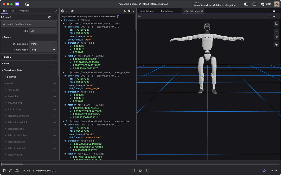
| 2 | Record MCAP and Open It in Foxglove | Log LowState, SportModeState, IMU, and commands into replayable telemetry |
| 3 | PlotJuggler for G1 Signals | Plot joint position, velocity, torque, IMU, command tracking, and delay |
| 4 | WBID and PD for G1 in MuJoCo | Design low-level control loops, gains, saturation, and stability checks |
| 5 | Upper-Body IK for G1 | Control arms and upper body, map joint indices, and check command safety |
| 6 | Sim-to-Real Checklist | Align simulation and hardware: domain, network, gains, timing, and safety |
Think of this article as the plumbing for the entire series. If the DDS topic is wrong, the domain is wrong, or the scene is not actually G1, every beautiful dashboard in the next articles is just wrong data drawn nicely.
How Unitree MuJoCo differs from a generic ROS simulator
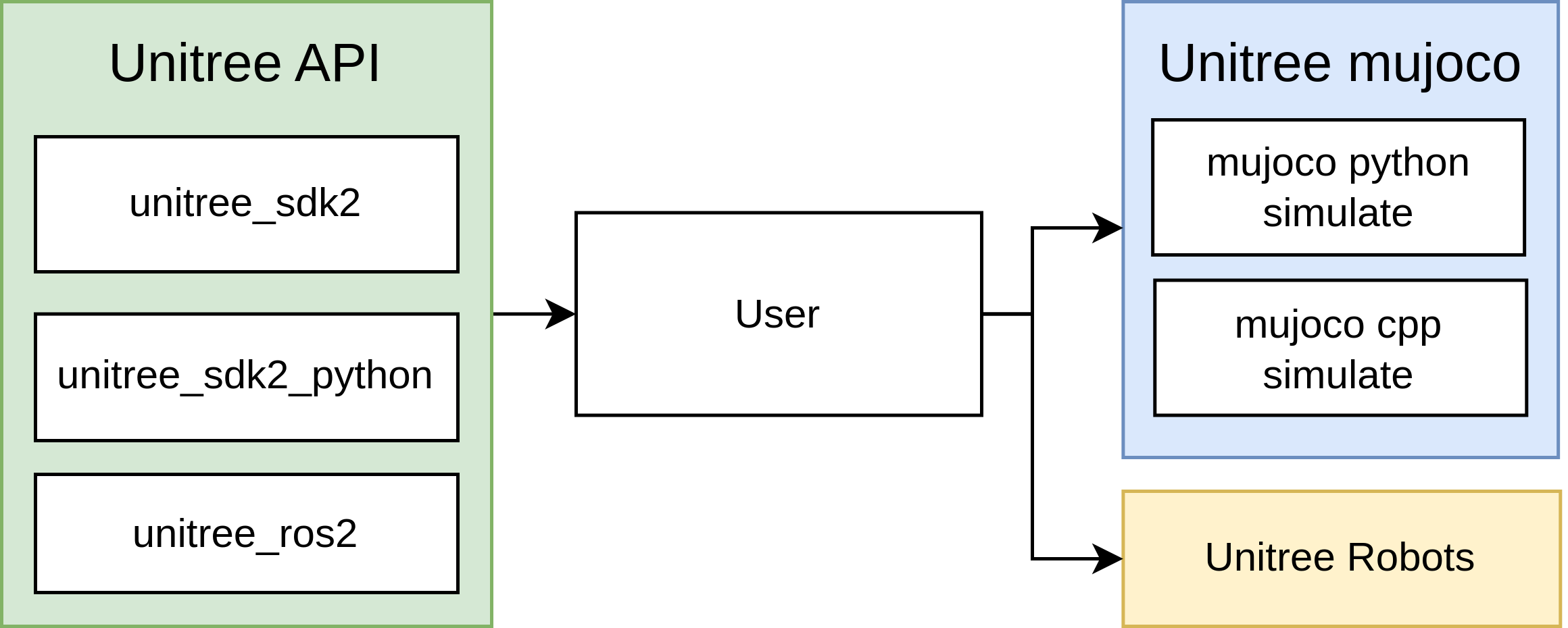
The official README describes unitree_mujoco as a simulator developed on top of Unitree SDK2 and MuJoCo. It does not merely expose a Python API for reading qpos and qvel. It creates a bridge so programs written with unitree_sdk2, unitree_ros2, or unitree_sdk2_python can communicate with the simulator in a way that resembles communication with a real robot. The repository has two simulator entry points:
| Directory | Role | When to use it |
|---|---|---|
simulate |
C++ simulator based on unitree_sdk2 and MuJoCo |
Use it when you want the closest SDK2 path, better performance, and full G1-specific topics |
simulate_python |
Python simulator based on unitree_sdk2_python and the mujoco package |
Use it for reading the flow, experiments, debugging, and teaching |
unitree_robots |
MJCF robot and scene files loaded by the simulator | Choose g1/scene.xml, g1/scene_23dof.xml, or g1/scene_29dof.xml |
example |
C++, Python, and ROS2 control examples | Use these to understand Unitree's sim-to-real pattern |
The most important detail is that the current README says the simulator mainly supports low-level development, especially for controller sim-to-real verification. That means you should think in terms of LowCmd and LowState, not a fake high-level command such as "walk to x,y,z." For G1, the README also states that G1 and H1-2 use unitree_hg IDL for low-level communication, while Go2, B2, H1, B2w, and Go2w use unitree_go IDL. If you copy a Go2 test program directly and run it against G1, the scene may load, but the message type may not match.
C++ configuration: simulate/config.yaml
The C++ configuration file currently contains these core fields:
robot: "go2"  # Robot name, "go2", "b2", "b2w", "h1", "go2w", "g1", "h2"
robot_scene: "scene.xml" # Robot scene, /unitree_robots/[robot]/scene.xml

domain_id: 1
interface: "lo"

use_joystick: 0
joystick_type: "xbox"
joystick_device: "/dev/input/js0"
joystick_bits: 16

print_scene_information: 1
enable_elastic_band: 0
For a beginner local G1 bring-up, start with:
robot: "g1"
robot_scene: "scene.xml"
domain_id: 1
interface: "lo"

use_joystick: 0
joystick_type: "xbox"
joystick_device: "/dev/input/js0"
joystick_bits: 16

print_scene_information: 1
enable_elastic_band: 0
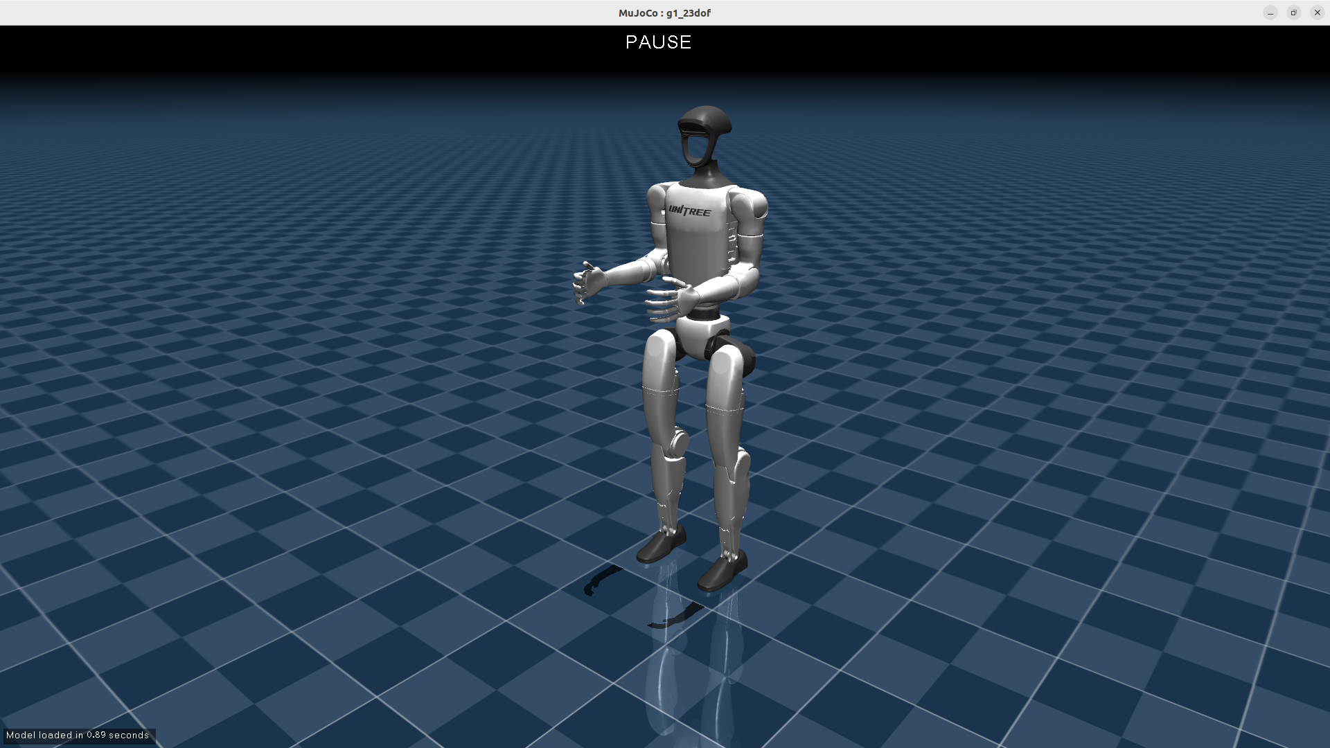
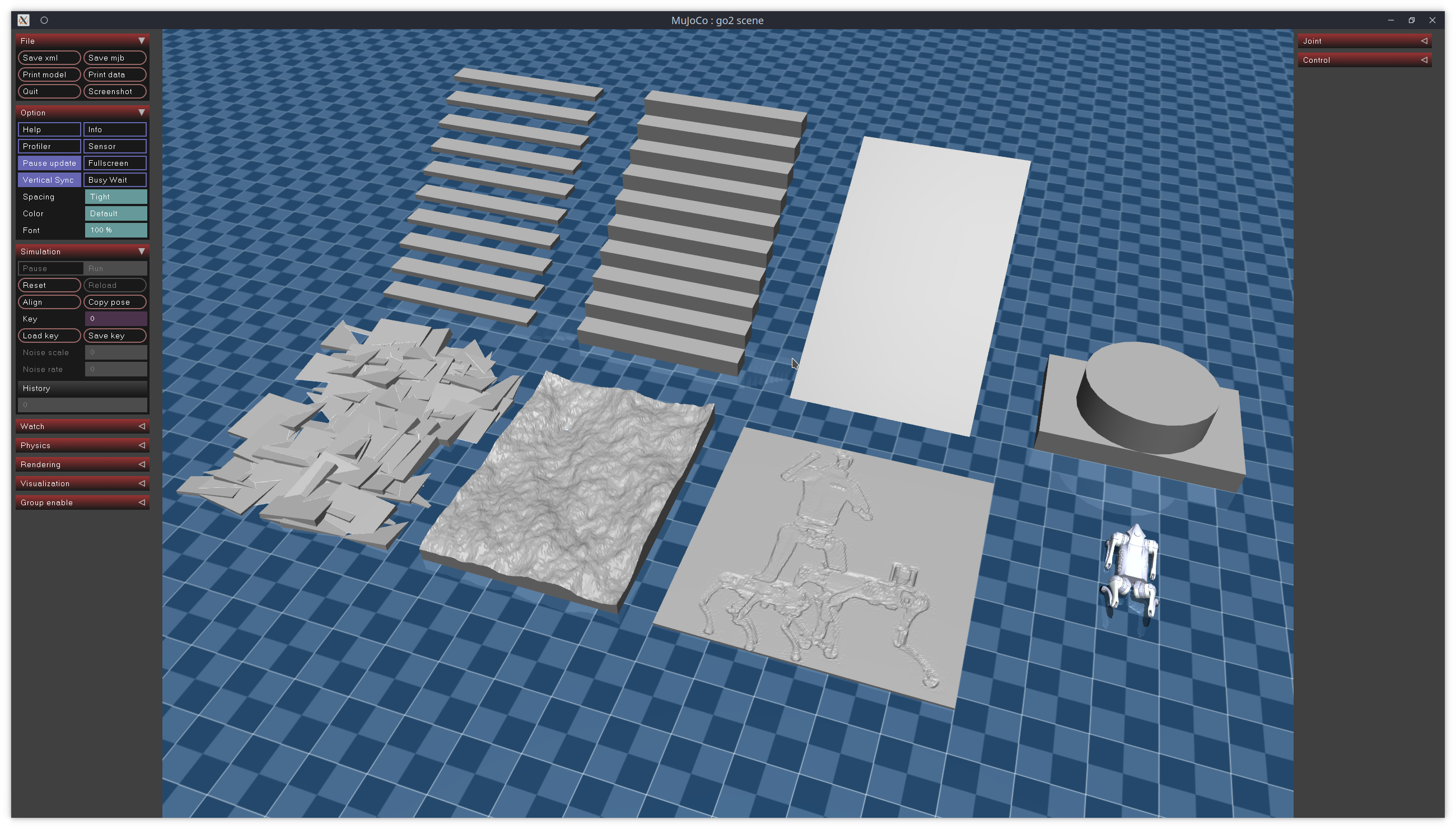
robot selects the subdirectory under unitree_robots. With robot: "g1", the simulator resolves scenes under unitree_robots/g1/. robot_scene is the scene file in that directory. For G1, the repository includes scene.xml, scene_23dof.xml, and scene_29dof.xml. The current scene.xml includes g1_29dof.xml and adds a ground plane, height fields, stairs, and obstacles. If you want to test 23DOF mapping, use scene_23dof.xml. If you need the 29DOF upper-body setup used later in this series, use scene_29dof.xml or the default scene.xml.
domain_id is the DDS domain. The README recommends separating the simulator from the real robot, because real Unitree hardware commonly uses default domain 0. This is a serious safety rule. For local simulation, domain_id: 1 reduces the chance that an experimental controller accidentally talks to real hardware on the same network. When you deploy to hardware, you switch domain and interface deliberately, together with a safety checklist.
interface is the network interface used by DDS. For local simulation, use "lo" for loopback. Your controller in another terminal must initialize SDK2 with the same domain and interface: C++ uses ChannelFactory::Instance()->Init(1, "lo"), and Python uses ChannelFactoryInitialize(1, "lo"). If the simulator uses domain_id: 1, interface: "lo" while your controller uses domain 0 or interface eth0, the processes will not see each other.
use_joystick controls whether the simulator emulates Unitree's wireless controller through an Xbox or Switch gamepad. If you do not have a gamepad plugged in, set it to 0. The README explicitly says use_joystick or USE_JOYSTICK should be set to 0 when there is no gamepad. This is a common beginner issue: the simulator starts, then fails or blocks around joystick initialization because a default config enables it.
Python configuration: simulate_python/config.py
The Python configuration is the equivalent:
ROBOT = "go2"
ROBOT_SCENE = "../unitree_robots/" + ROBOT + "/scene.xml"
DOMAIN_ID = 1
INTERFACE = "lo"

USE_JOYSTICK = 1
JOYSTICK_TYPE = "xbox"
JOYSTICK_DEVICE = 0

PRINT_SCENE_INFORMATION = True
ENABLE_ELASTIC_BAND = False

SIMULATE_DT = 0.005
VIEWER_DT = 0.02
For a beginner G1 run, change it to:
ROBOT = "g1"
ROBOT_SCENE = "../unitree_robots/" + ROBOT + "/scene.xml"
DOMAIN_ID = 1
INTERFACE = "lo"

USE_JOYSTICK = 0
JOYSTICK_TYPE = "xbox"
JOYSTICK_DEVICE = 0

PRINT_SCENE_INFORMATION = True
ENABLE_ELASTIC_BAND = False

SIMULATE_DT = 0.005
VIEWER_DT = 0.02
SIMULATE_DT is the MuJoCo timestep. In the Python source, mj_model.opt.timestep = config.SIMULATE_DT, and the physics thread repeatedly calls mujoco.mj_step(mj_model, mj_data). The config comment notes that the timestep must be larger than the runtime of one viewer.sync() if you want reliable simulation. VIEWER_DT = 0.02 means the viewer syncs at about 50 FPS. When you are learning, do not reduce the timestep aggressively just because "500 Hz looks better." If your machine cannot render or the Python thread jitters, the telemetry you record in parts 2 and 3 will contain timing artifacts.
PRINT_SCENE_INFORMATION = True is useful on the first run. The bridge prints link, joint, actuator, and sensor indices. For G1, that list helps you connect MJCF names with indices in LowCmd.motor_cmd and LowState.motor_state. The repository also provides unitree_robots/g1/g1_joint_index_dds.md, which lists motor order for the 23DOF and 29DOF versions. For example, the 29DOF list starts with L_LEG_HIP_PITCH, L_LEG_HIP_ROLL, L_LEG_HIP_YAW, L_LEG_KNEE, then ankle joints, right leg, waist, and both arms. Do not hardcode joint indices from memory if you change scenes.
What the C++ entry point does
In simulate/src/main.cc, the program reads config, accepts command-line overrides, resolves a relative scene into unitree_robots/<robot>/<scene>, and then runs two major flows: physics/viewer and the Unitree SDK2 bridge. The helper in param.h allows quick overrides:
./unitree_mujoco -r g1 -s scene.xml -i 1 -n lo
The flags map directly to the config:
| Flag | Config field | Example |
|---|---|---|
-r |
robot |
-r g1 |
-s |
robot_scene |
-s scene.xml |
-i |
domain_id |
-i 1 |
-n |
interface |
-n lo |
The bridge thread calls:
unitree::robot::ChannelFactory::Instance()->Init(
  param::config.domain_id,
  param::config.interface
);
Then the source chooses a bridge by robot type. If robot == "g1", it creates G1Bridge; otherwise, for a robot such as Go2, it creates the corresponding non-G1 bridge. This means robot: "g1" affects more than meshes or visuals. It also selects the message wrapper and G1-specific outputs such as the secondary IMU.
The physics thread calls mj_step(m, d) to advance MuJoCo. The bridge reads sensors from mj_data_->sensordata, publishes state to DDS, receives LowCmd from DDS, and writes control into mj_data_->ctrl. The low-level bridge uses a control expression equivalent to:
ctrl[i] = tau
        + kp * (q_des - q_measured)
        + kd * (dq_des - dq_measured)
So LowCmd is not pure torque only. You can send feedforward torque tau, desired position q, desired velocity dq, and gains kp, kd. Part 4 will cover gain selection and saturation in detail. For now, remember that the simulator is executing Unitree-style low-level command semantics, not a hand-made ROS command topic.
What the Python entry point does
simulate_python/unitree_mujoco.py is easier for beginners to read. It loads the model with:
mj_model = mujoco.MjModel.from_xml_path(config.ROBOT_SCENE)
mj_data = mujoco.MjData(mj_model)
Then it launches the viewer, sets the timestep, and creates two threads:
viewer_thread = Thread(target=PhysicsViewerThread)
sim_thread = Thread(target=SimulationThread)
Inside SimulationThread, the code calls:
ChannelFactoryInitialize(config.DOMAIN_ID, config.INTERFACE)
unitree = UnitreeSdk2Bridge(mj_model, mj_data)
If USE_JOYSTICK is enabled, the bridge initializes the joystick. If PRINT_SCENE_INFORMATION is enabled, it prints scene information. The main loop locks shared data, calls mujoco.mj_step, releases the lock, and sleeps for the remaining timestep. The viewer thread uses the same lock, calls viewer.sync(), and sleeps according to VIEWER_DT. This simple design is enough to teach timing: physics stepping and viewer rendering are not the same job. If telemetry looks jittery, check both the physics timestep and viewer sync.
One version note matters. The README lists IMUState at rt/secondary_imu for G1. In the current C++ source checked for this article, G1Bridge creates IMUState_t("rt/secondary_imu") and publishes quaternion, RPY, gyroscope, and accelerometer from secondary_imu_* sensors. In the Python bridge source checked here, the low-state, high-state, and wireless controller paths are more explicit, while secondary IMU support can depend on the branch or version you use. If part 2 of your workflow needs complete rt/secondary_imu logging, prefer the C++ simulator or inspect your Python bridge before assuming the topic exists.
Real topics and messages to remember
The official README lists the Unitree SDK2 messages supported by the simulator:
| Message | Common topic | Meaning |
|---|---|---|
LowCmd |
rt/lowcmd |
Motor command: q, dq, tau, kp, kd, mode |
LowState |
rt/lowstate |
Motor state: position, velocity, estimated torque, torso IMU |
SportModeState |
rt/sportmodestate |
Robot position and velocity, useful for analyzing controllers in simulation |
IMUState |
rt/secondary_imu |
G1 secondary IMU with quaternion/RPY/gyro/accelerometer |
WirelessController |
rt/wirelesscontroller |
Emulated gamepad state when joystick support is enabled |
Two details are easy to miss. First, SportModeState may not be readable on the real robot after the built-in motion control service is turned off, but the simulator keeps it so you can analyze controller position and velocity. Using it in a simulation dashboard is reasonable, but do not make a hardware controller depend on it unless your real robot mode actually provides it.
Second, G1 uses unitree_hg IDL for low-level messages. If you write your own Python subscriber or publisher, import the correct message family. The repository's Python bridge chooses unitree_hg when the motor count exceeds the Go IDL threshold, but a standalone test script can still be wrong. A common symptom is that topic names look correct, but callbacks never run or deserialization fails.
Beginner bring-up sequence
Move slowly and verify one thing at a time:
- Install dependencies according to the README:
unitree_sdk2for C++,unitree_sdk2_pythonfor Python, MuJoCo, and joystick packages if needed. If Python cannot locate CycloneDDS, followunitree_sdk2_pythoninstructions forCYCLONEDDS_HOMEorCMAKE_PREFIX_PATH. - Pick one simulator first. Use
simulate_pythonif your goal is reading the flow quickly. Usesimulateif your goal is the closest SDK2 path and the clearest G1-specific topics. - Change config to
robot: "g1",robot_scene: "scene.xml",domain_id: 1,interface: "lo", anduse_joystick: 0. - Run the simulator and confirm the G1 viewer opens. If scene printing is enabled, inspect the actuator and sensor counts.
- Open a second terminal and run a subscriber or test program with the same domain and interface. Do not use domain
0if the simulator is on1. - Only after you can read
LowState, publish a very smallLowCmd, such as a low-gain command or a single-joint torque check in a safe setup.
Minimal mental model:
Terminal A
  unitree_mujoco / unitree_mujoco.py
  DOMAIN_ID=1, INTERFACE=lo
        |
        | DDS topics
        v
Terminal B
  logger / controller / Foxglove bridge
  DOMAIN_ID=1, INTERFACE=lo

rt/lowcmd          controller -> simulator
rt/lowstate        simulator -> logger/controller
rt/sportmodestate  simulator -> logger
rt/secondary_imu   G1 bridge  -> logger/controller
If no data appears, check the basics first: same domain, same interface, correct message IDL, joystick disabled when no gamepad is attached, correct G1 scene, and a controller publishing to rt/lowcmd rather than to a custom ROS topic name.
Choosing robot_scene for later articles
unitree_robots/g1/scene.xml currently includes g1_29dof.xml and adds several terrain elements: ground plane, obstacles, stairs, rough boxes, and height fields. That is useful for locomotion and telemetry because SportModeState, IMU, and joint loads change clearly when the robot interacts with uneven ground. But when you first debug joint-level PD, a complex scene can hide simple mistakes. A practical workflow is:
| Goal | Suggested scene |
|---|---|
| Verify DDS, topics, and subscribers | scene.xml |
| Check 23DOF joint index mapping | scene_23dof.xml |
| Work on 29DOF upper-body control | scene_29dof.xml or scene.xml |
| Plot signals on terrain | scene.xml |
For this series, the default assumption is g1 with scene.xml so we have the full telemetry path. In part 5, when we move to upper-body IK, we will revisit the 29DOF joint indices and the command mapping for shoulders, elbows, and wrists.
Conclusion
The key lesson in part 1 is a shift in perspective: G1 MuJoCo is not just a 3D robot standing in a viewer. It is a low-level DDS endpoint that emulates important parts of a real Unitree robot interface. robot and robot_scene select the model; domain_id and interface decide whether processes can discover each other; use_joystick decides whether an emulated wireless controller is published; and LowCmd, LowState, SportModeState, and IMUState are the messages you will log, plot, and control against in the next articles.
In part 2, we will use these topics to record MCAP and open the data in Foxglove. In part 3, the same data will go into PlotJuggler so we can inspect tracking, delay, and noise. Once the DDS foundation is correct, visualization and control become much less ambiguous.